XP-142E System Reference-SYS-XP142-2.0E.pdf.pdf - 第68页
3.6.3 [Feeder Data Info] Screen (ESR0207h) This screen is used to verify device types and slot positions used in production, and to check for parts-out errors. Procedure 1. At the [Main] screen, press [Production] then […

3.6 Supply of Tape Parts
(ESR0221e)
The MFU is clamped to, and unclamped from, the machine by an air cylinder driven
mechanism. The Side 1 procedure is explained below, but the procedure is identical for
Side 2.
Note: This function is disabled on machines equipped with a fixed device table.
3.6.1 Changing an MFU
Clamping Procedure
1. Open the machine’s front door, then gently push the MFU into its machine
docking position.
2. At the [Main] screen, press [Manual Operation], then [STAGE1 MFU Clamp] to
display a start confirmation dialog box. Press the START switch to clamp the
MFU.
Unclamping Procedure
1. From the [Main] screen, select [Machine Operation] - [STAGE1 MFU Unclamp].
A “START confirmation” dialog box then displays.
2. Press [START] to unclamp the machine’s front-side MFU.
The following message then displays: “Work after the door of the front is opened.”
3. Open the door at the side where the MFU was unclamped, then press [OK] on the
display screen.
4. Gently pull the MFU out of the machine.
Note: Only the MFU on the side of the machine that is enabled can be removed.
3.6.2 Tape Cutter Manual Operation
1. At the [Main] screen, select [Manual Operation], then [Tape Cutter Stage1].
A confirmation dialog is displayed.
2. Push the START button to cut the feeder tape on Side 1 of the machine.
Note: This command is restricted to the control panel on the same side of the machine as
the tape cutter to be activated.
Part 2 Chapter 3 Changeover
Edition 2.0 2-3-13 XP-142E System Reference
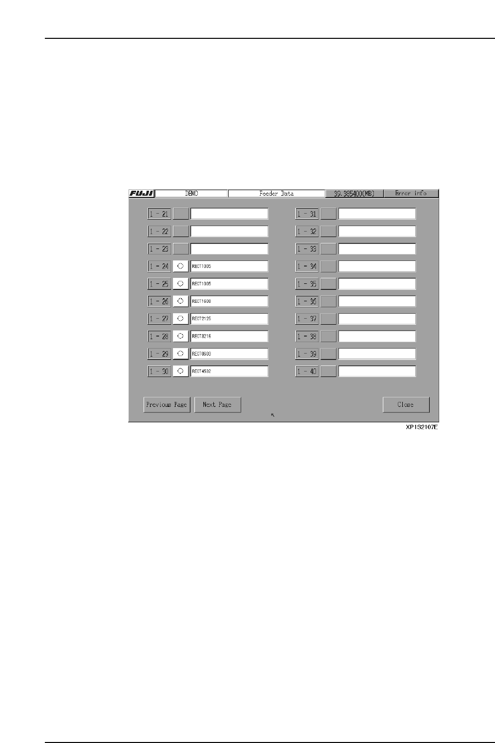
3.6.3 [Feeder Data Info] Screen
(ESR0207h)
This screen is used to verify device types and slot positions used in production, and to
check for parts-out errors.
Procedure
1. At the [Main] screen, press [Production] then [Feeder Data Info] to display the
[Feeder Data] screen.
2. Each screen contains boxes that indicate the status of 20 feeders on the MFU. From
left to right are the slot number, the part status, and a comment area.
• The Stage and Slot numbers are displayed with the following color codes.
Red: Original slot
Blue: Next slot
Black: Unused slot
• When a part runs out, an [X] is displayed. After loading more parts, push the [X]
to return the status to normal [O].
Part 2 Chapter 3 Changeover
Edition 2.0 2-3-14 XP-142E System Reference
Part 2 Chapter 3 Changeover
Edition 2.0 2-3-15 XP-142E System Reference
3.7 Automatic Offsetting of Pickup Position
For reasons such as variation in part position and nozzle bend, a part may not be
centered on the nozzle when picked up. The machine has a function that can be used to
automatically offset X- and Y- pickup positions to stabilize pickup.
If the part data item [Pick-up Auto Offset] is set to [0: Yes], then pickup position offsets
are calculated based on vision processing results, and subsequent pickups of the same
part are automatically offset.
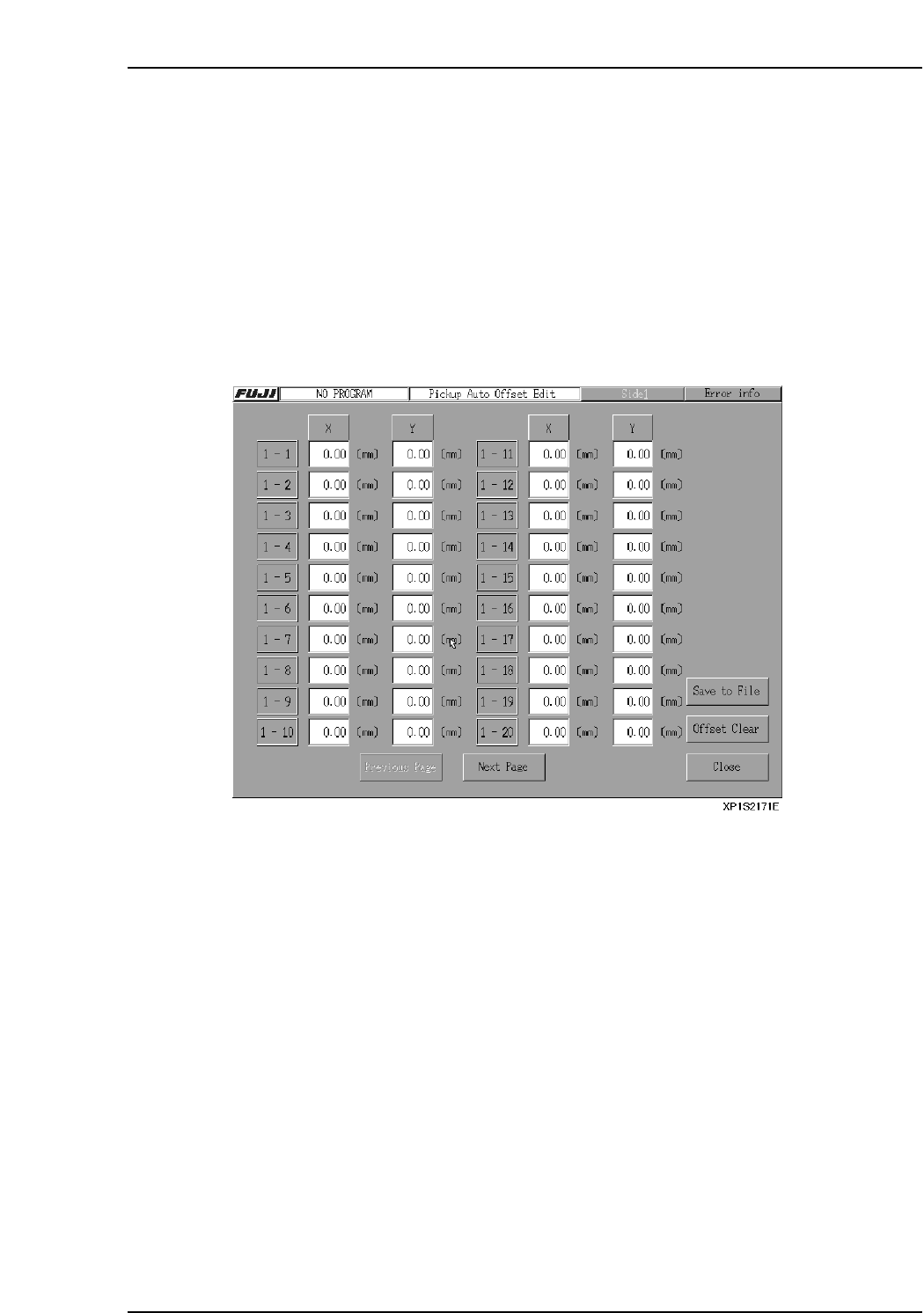
Pickup Auto Offset Edit
The offset distance can been seen and edited at the [Pickup Auto Offset Edit] screen.
At the [Production] screen, select [Pickup Auto Offset] to open the [Pickup Auto Offset
Edit] screen. The commands at this screen can be used to see and edit the offsets.
[Close] button
Select this button to exit the [Pickup Auto Offset Edit] screen. A dialog will then appear
reminding you that the offsets will be saved.
[Previous Page] button
Select this button to return the display to the previous page.
[Next Page] button
Select this button to advance the display to the next page.
[Save to File] button
Select this button to save all pickup offset data to an MS Excel format file.
Notes:
• If a pickup offset data file already exists on the floppy disk, an overwrite confirmation dialog
appears.
• If a pickup offset data file already exists on the floppy disk and the file is protected, an error
message will appear.
[Offset Clear] button
Selecting this button will reset all of the offsets to 0.
When this button is selected, a confirmation dialog appears before the offsets are reset.