XP-142E System Reference-SYS-XP142-2.0E.pdf.pdf - 第49页
2.1.9 T ape Cutter The procedure for specifying tape cutter settings is explained below. Procedure 1. At the [Main] screen, select [Maintenance A] - [Operation Settings] to display the [Operation Settings] screen. 2. Pre…

2.1.8 Stage Mode (Option)
This setting specifies the stage where part pickups are to occur. The stage mode can be
set as “JOINT” or “AA”.
JOINT: Both stage 1 and 2 are used in a linked manner. This mode is used when a
single stage cannot hold all the parts.
AA: Both stage 1 and 2 are loaded with the parts to be used by the production
program, and when one stage runs out of parts, the other stage is used. This
mode reduces the machine stop time for part supply.
Recovery processing occurs in this stage change mode (AA) as described
below.
Auto recovery: If the other stage is available after the recovery count limit is
reached, the pickup operation moves to the other stage with
production continuing without a machine stop.
Error stop: Operation is stopped each time an error or a “no parts”
condition is detected.
Error pass: Operation is not stopped when an error or a “no parts”
condition is detected. Stage changes do not occur, even if
operating in the stage change mode.
Procedure
1. At the [Main] screen, select [Maintenance A] - [Operation Settings], then display
the [Select Mode] screen.
2. Each time the [Stage Mode] button is pressed, the mode alternates between
[JOINT] and [AA]. Select the desired mode.
3. Press [Close] to return to the [Main] screen.
Note: The stage mode display can be turned on and off by a Proper data setting.
■ Original Stage Setting
When the stage mode is set as “AA”, the stage where parts are first picked up after
program change (original stage) must be selected. The original stage can be set as “stage
1” or “stage 2”.
Stage 1: Part pickup begins from stage 1.
Stage 2: Part pickup begins from stage 2.
Procedure
1. At the [Main] screen, select [Maintenance A] - [Operation Settings], then display
the [Select Mode] screen.
2. Each time the [Original Stage] button is pressed, the setting alternates between
“stage 1” and “stage 2”. Select the desired stage.
3. Press [Close] to return to the [Main] screen.
Note: The original stage display can be turned on and off by a Proper data setting.
Part 2 Chapter 2 Settings Prior to Start Production
Edition 2.0 2-2-6 XP-142E System Reference
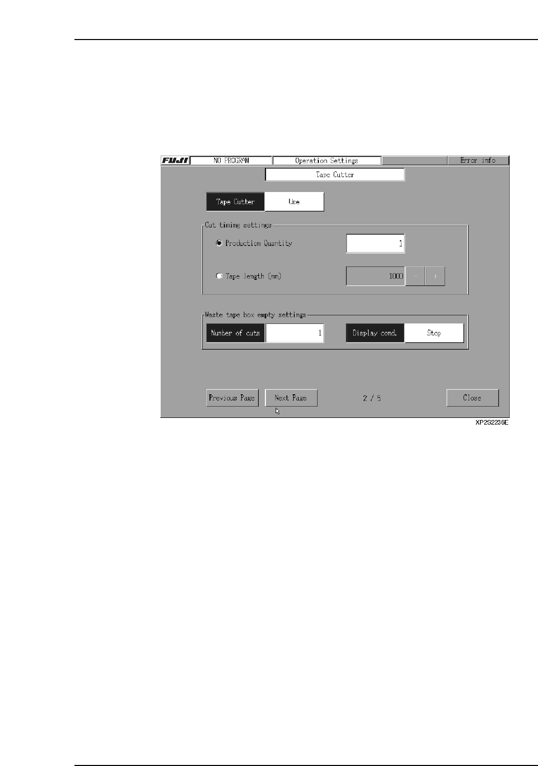
2.1.9 Tape Cutter
The procedure for specifying tape cutter settings is explained below.
Procedure
1. At the [Main] screen, select [Maintenance A] - [Operation Settings] to display the
[Operation Settings] screen.
2. Press the [Next Page] button to display the [Tape Cutter] screen.
3. Click on the area next to the “Tape Cutter” item, then make the “Use/Not Used”
selection.
4. At the “Cut Timing Setting” area, specify the cutter operation conditions. If cutter
operation is to occur when the scheduled panel production quantity is reached,
select “Production Quantity”, then specify the count value. (The setting range is 0
~ 99999. If a setting of “0” is specified, tape cutter operation will not occur.) If
cutter operation is to occur when a specified tape length is reached, select “Tape
Length”, then specify the desired length value. Cutter operation occurs when any
tape reaches this length, even if production is in progress.
Ex. If the tape length is set to 100 mm, and the tape lengths of feeders A, B, and
C on Stage1 are 100, 80, and 60 mm, then the tape cutter will cut, because
the 100 mm of tape on feeder A meets the setting. After the tape is cut, the
tape length counters are all reset to 0 mm.
[+]: Each time this key is pressed, the value increases by 50. If pressed when the
value is 1000, the value becomes 0.
[ - ]: Each time this key is pressed, the value decreases by 50. If pressed when the
value is 0, the value becomes 1000.
If a “0” value is specified, cutter operation will not occur. (Units: mm)
5. Click on the area next to the “Number of cuts” area to specify the tape cutter
operation count at which a message displays, notifying the operator to empty the
waste tape box. (Setting range is 0 ~ 99999. If “0” is specified, the message does
not display.)
6. Select the machine status action which is to occur when the tape cutter operation
count reaches the setting value.
Warning: Waste tape box warning displays, and machine operation continues.
Stop: Waste tape box warning displays, machine operation stops.
Part 2 Chapter 2 Settings Prior to Start Production
Edition 2.0 2-2-7 XP-142E System Reference
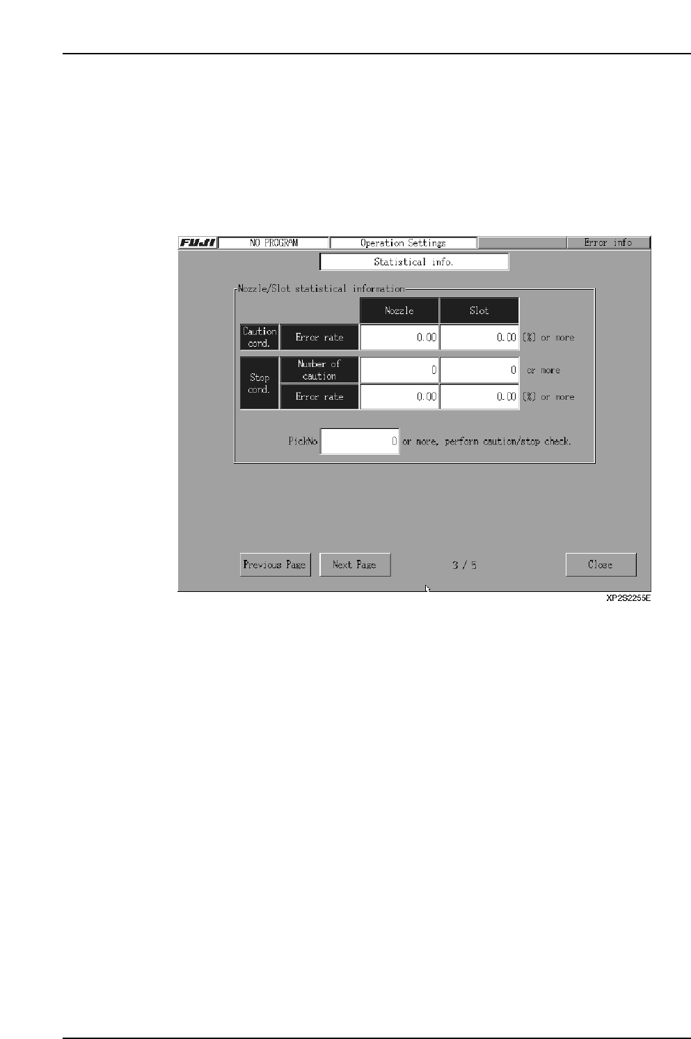
2.1.10 Statistical Information
The statistical information function is used to obtain information about nozzle and slot
errors. The procedure for specifying statistical information settings is given below.
Procedure
1. At the [Main] screen, select [Maintenance A] - [Operation Settings] to display the
[Operation Settings] screen.
2. Press the [Next Page] button to display the [M/C Stat Info] screen.
3. In the textbox next to the “PickNo” item, specify the minimum pickup count at
which an error check is to occur. An error check will occur when a given slot or
nozzle reaches this pickup operation count. The setting range is 0 ~ 10000. When
set as “0”, the minimum pickup count for a caution check will be [1 / caution
conditions error rate] x [100], and the minimum pickup count for a stop check will
be [1 / stop conditions error rate] x [100].
4. In the textboxes beside the caution conditions error rate item, specify the nozzle
and slot error rates at which cautions are to occur. The setting range is 0.00 ~ Stop
conditions error rate. When the stop conditions error rate is 0.00, a setting of up to
100.00 can be specified. When set as “0.00”, there are no caution displays.
5. In the textboxes beside the stop conditions “number of cautions” item, specify the
number of cautions at which the machine is to be stopped. The machine stops
when the number of nozzle cautions reaches the setting value specified at the
Nozzle textbox. The setting range is 0 ~ Total number of nozzles. When set as
“0”, there are no caution count checks. The machine also stops when the number
of slot cautions reaches the setting value at the Slot textbox. The setting range is 0
~ Number of slots. When set as “0”, there are no caution count checks.
6. In the textboxes beside the stop conditions “number of cautions” item, specify the
nozzle and slot error rates at which the machine is to be stopped. The setting
range is 0.00 and “number of caution conditions ~ 100.00. When set as “0.00”,
there are no count checks.
Part 2 Chapter 2 Settings Prior to Start Production
Edition 2.0 2-2-8 XP-142E System Reference