XP-142E System Reference-SYS-XP142-2.0E.pdf.pdf - 第185页
Setting Item Explanations Side Specify the body side where the element is located. Position X, Position Y Specify the X/Y direction position of the element center, as measured from the body center. (-99.99 mm ~ 99.99 mm)…
Part 3 Chapter 3 Editor
Edition 2.0 3-3-29 XP-142E System Reference
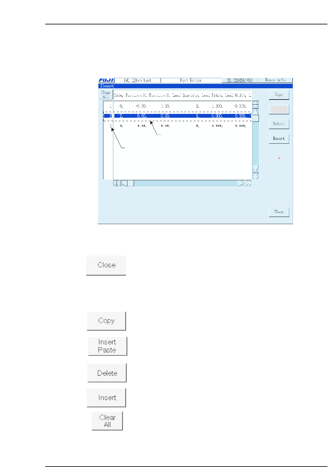
Element
An “element” is a group of uniform, constant-pitch leads. Because a part body may
comprise several elements, each of these elements is assigned a number to distinguish
between them. Element data includes the lead length, width and pitch.
Operation Button Explanations
Closes the dedicated element data editor and returns to the part data
editor.
The following buttons apply to the line which has been selected in the selection area at
the left side of the screen.
Copies the selected line to the clipboard.
Pastes the clipboard data above the selected line.
Deletes the selected line, and moves the subsequent lines up to fill the
vacated space.
Inserts a new (blank) line above the selected line.
Cancels all selections.
XP2S2210Ea
Specify new data
Select area
Insert
Paste
Setting Item Explanations
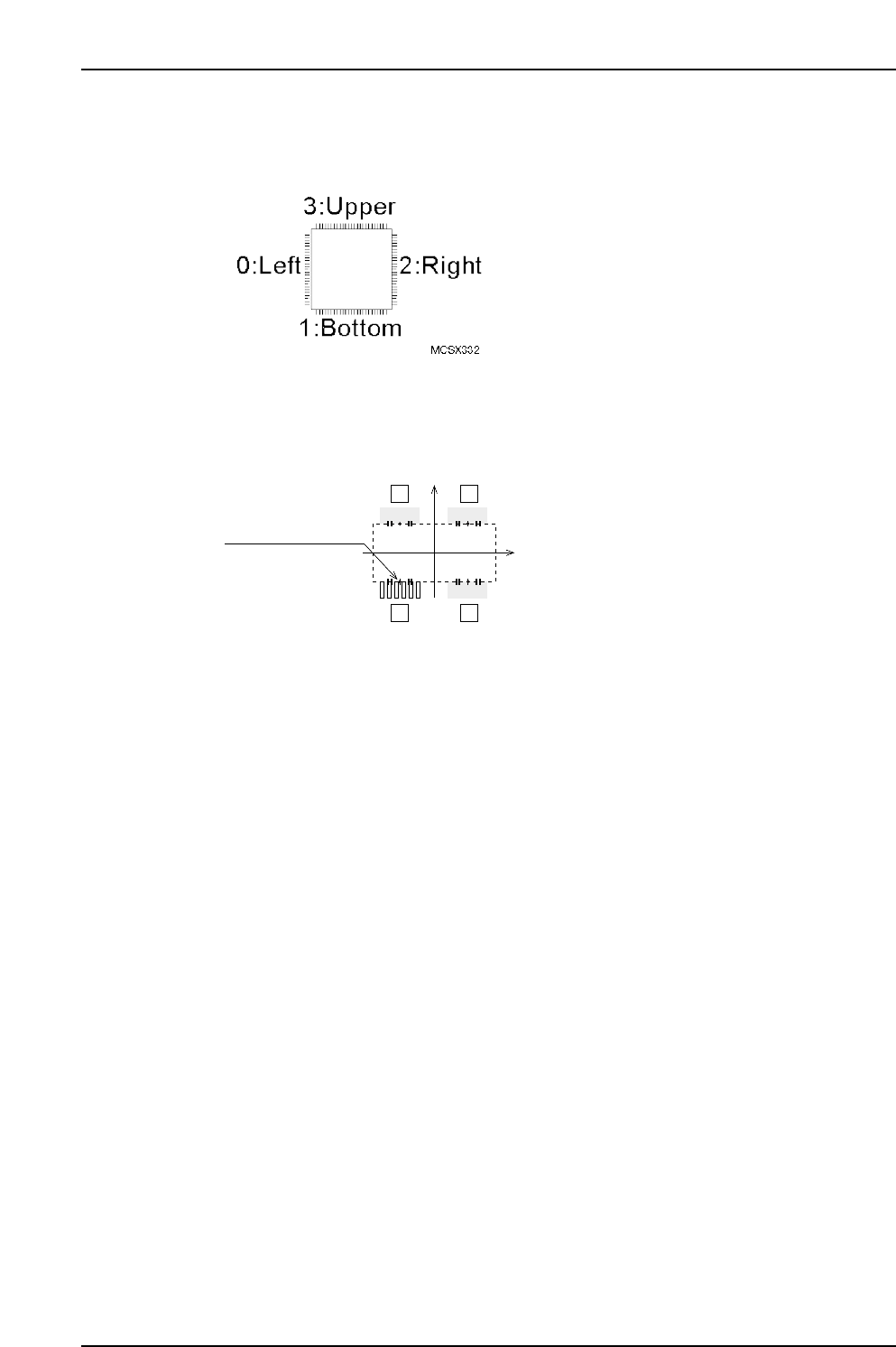
Side
Specify the body side where the element is located.
Position X, Position Y
Specify the X/Y direction position of the element center, as measured from the body
center. (-99.99 mm ~ 99.99 mm)
Lead Quantity
Specifies the number of leads in the element. (0 ~ 128)
Lead Pitch
Specifies the pitch between the leads. (0.000 mm ~ 99.999 mm)
Lead Width
Specifies the lead width. (0.000 mm ~ 99.999 mm)
Lead Length
Specifies the lead length. (0.000 mm ~ 99.999 mm)
Lead Width Tolerance (Presently not supported)
Specifies the lead width tolerance. (0.000 mm ~ 99.999 mm)
Lead Length Tolerance
Specifies the lead length tolerance. (0.000 mm ~ 99.999 mm)
If a setting of “0” is entered, the lead length tolerance will automatically be set as 30 % of
the lead length. This setting is only used with vision type 100.
Lead Center Tolerance
Enter the lead’s bend tolerance. (0.000mm ~ 99.999mm)
If a setting of “0” is entered, the lead center tolerance will automatically be set as 30% of
the lead length. This setting is only used with vision type 100.
P Pattern
This data defines how the lead image is viewed. (0 ~ 255)
When using Vision Type 100 (QF & Connector: Frontlight processing), enter a setting of
“14”. If the lead is dark and the background is light, enter a setting of “13”.
Lead element
12
43
MCSX333Ea
(PositionX, PositionY)
(0, 0)
Part 3 Chapter 3 Editor
Edition 2.0 3-3-30 XP-142E System Reference
Part 3 Chapter 3 Editor
Edition 2.0 3-3-31 XP-142E System Reference
Process
Maximum Nozzle Diameter
Specifies the maximum size of the nozzle used to handle the parts. (0.0 mm ~ 99.9 mm)
Minimum Nozzle Diameter
Specifies the minimum size of the nozzle used to handle the parts. (0.0 mm ~ 99.9 mm)
Nozzle Name
To use a specific nozzle, select it from the name list. (Max. of 15 characters.)
Pick-up Auto Offset
Specifies whether or not the automatic pickup offset function is to be used.
YES: Auto offset function is used : 0
NO: Auto offset function is not used : 1
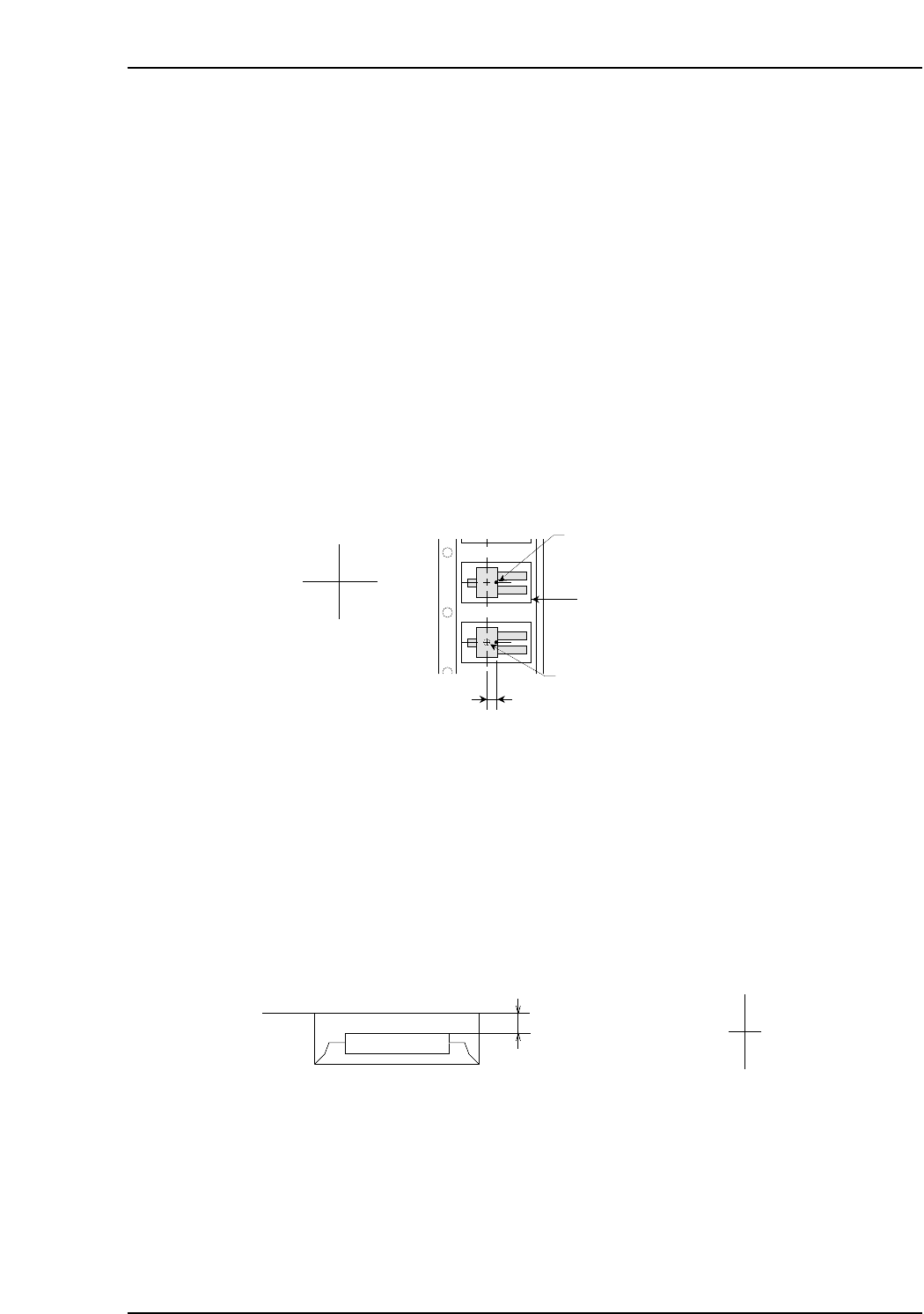
Pick-up Point Offset X
Specify this setting in order to pick up a part at a position other than the slot’s X-
direction center. Direction”0” is the reference part direction when setting the offset. To
specify a 5mm offset to the right, enter “5”. (-12.7 mm ~ 12.7 mm)
Pick-up Point Offset Y
Specify this setting in order to pick up a part at a position other than the slot’s Y-
direction center. ”Direction 0” is the reference part direction when setting the offset. To
specify a 5mm offset in the “back” direction, enter “5”. (-12.7 mm ~ 12.7 mm)
Pick-up Point Offset Z
Specify this setting in order to pick up a part at a height other than the slot’s standard
height. For example, a downward offset of 1 mm can be specified by entering “-1”.
(-12.7 mm ~ 12.7 mm)
Offset value
MCSX336E
Z (+)
Z (-)
Cavity center
(Pick-up point when Pick-up Point
Offset X is set to "0" )
Cavity
Pick-up Point Offset X
Nozzle pick-up point
X (-) X (+)
MCSX335Eb