XP-142E System Reference-SYS-XP142-2.0E.pdf.pdf - 第165页
Moves the Y-axis in the minus direction, either continuously at low speed, or in 0.01 mm steps. Moves the Y-axis in the minus direction, either continuously at medium speed, or in 0.1 mm steps. Moves the Y-axis in the mi…
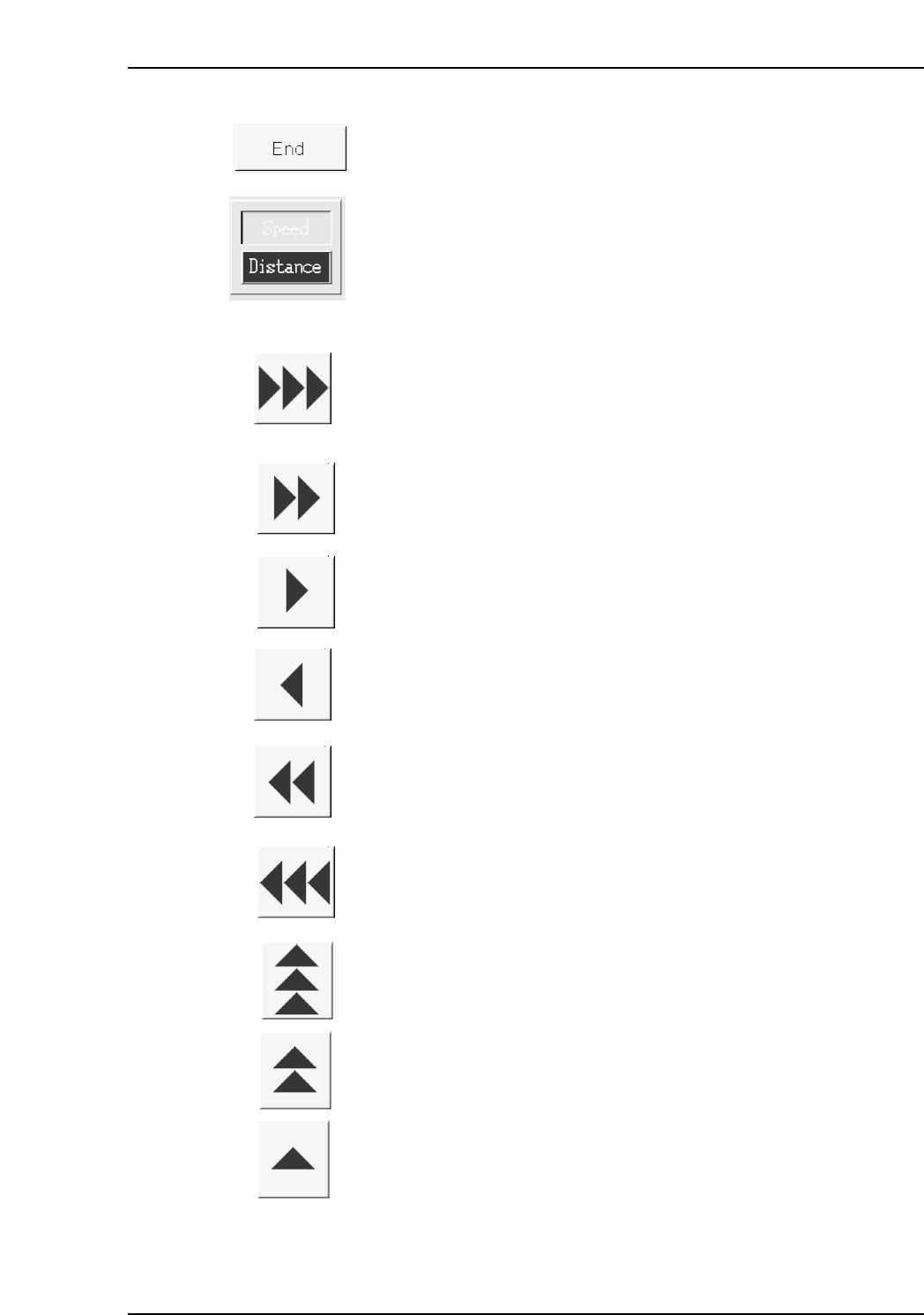
Ends the teaching operation without registering any data.
Specifies the JOG mode for the X,Y-axes. The color of the arrow
buttons change in accordance with this mode setting.
When in the [Distance] mode (blue buttons), axis travel is performed
over the indicated distance each time one of the following buttons is
pressed. When in the [Speed] mode (green buttons), axis travel
continues (at the indicated speed) for as long as a button is pressed.
Moves the X-axis in the plus direction, either continuously at high
speed, or in 1 mm steps.
Moves the X-axis in the plus direction, either continuously at medium
speed, or in 0.1 mm steps.
Moves the X-axis in the plus direction, either continuously at low speed,
or in 0.01 mm steps.
Moves the X-axis in the minus direction, either continuously at low
speed, or in 0.01 mm steps.
Moves the X-axis in the minus direction, either continuously at medium
speed, or in 0.1 mm steps.
Moves the X-axis in the minus direction, either continuously at high
speed, or in 1 mm steps.
Moves the Y-axis in the plus direction, either continuously at high
speed, or in 1 mm steps.
Moves the Y-axis in the plus direction, either continuously at medium
speed, or in 0.1 mm steps.
Moves the Y-axis in the plus direction, either continuously at low speed,
or in 0.01 mm steps.
Part 3 Chapter 3 Editor
Edition 2.0 3-3-9 XP-142E System Reference

Moves the Y-axis in the minus direction, either continuously at low
speed, or in 0.01 mm steps.
Moves the Y-axis in the minus direction, either continuously at medium
speed, or in 0.1 mm steps.
Moves the Y-axis in the minus direction, either continuously at high
speed, or in 1 mm steps.
Part 3 Chapter 3 Editor
Edition 2.0 3-3-10 XP-142E System Reference
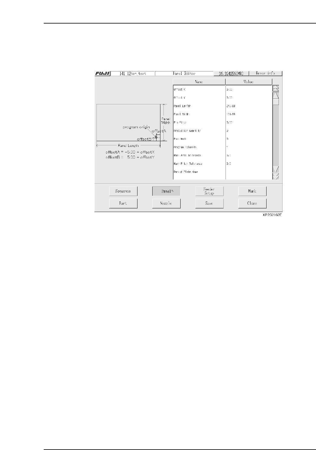
3.3 Panel Editing
(ESR0705g)
The Panel data editor is used to specify information about the panel on which parts are
to be placed.
Setting Item Explanations
Offset X
If a sequence coordinate is entered relative to a reference point other than the Fuji
program’s origin point (-5 mm in X-direction, or +5 mm in Y-direction, measured from
panel’s bottom right corner), an X-offset value must be entered, representing the distance
from the Fuji program’s origin point to the reference point which was used.
(-600.00 mm ~ 600.00 mm)
Offset Y
If a sequence coordinate is entered relative to a reference point other than the Fuji
program’s origin point (-5 mm in X-direction, or +5 mm in Y-direction, measured from
panel’s bottom right corner), an Y-offset value must be entered, representing the distance
from the Fuji program’s origin point to the reference point which was used.
(-600.00 mm ~ 600.00 mm)
Panel Size X
Specifies the panel’s X-direction size. (80.00 mm ~ 457.00 mm)
Panel Size Y
Specifies the panel’s Y-direction size. (50.00 mm ~ 356.00 mm)
Pin Pitch
Enter the distance between the reference hole (pin) and the secondary hole (pin).
(0.00 ~ 457.00)
Part 3 Chapter 3 Editor
Edition 2.0 3-3-11 XP-142E System Reference