XP-142E System Reference-SYS-XP142-2.0E.pdf.pdf - 第168页
3.4 Editing Feeder Setup Data (ESR0706e) The Feeder Setup Editor is used to specify which part is to be set in which slot. Operation Button Explanations Searches the feeder setup for a specified character string in the f…

Production Quantity
The production quantity can be specified here. If 0 is specified, then the [Scheduled
Panels] setting (in the Operation Settings screen) is enabled. (0 - 65000)
Pass Mode
Specified during Pass mode operations. When specified, the panels pass through the
machine without parts being mounted (conveyor operation only).
0: No Pass Not to perform pass through operation
1: Pass Perform pass through operation
Program Polarity
This setting determines whether or not the “standardized program method” (polarity
function) is used.
0: No Not to use program polarity function
(This setting currently is not supported. Production will not start if this is
set to “0”.)
1: Yes Use program polarity function
Refer to “Polarity function” for more detail.
Mark Identification Error Check Area
Specifies the tolerance for the area where checks for mark identification errors occur.
(0.0 ~ 10.0)
The identification check is not completed if the value is set to 0.0.
Mark Pitch Shift Tolerance
Specifies the tolerance range for shifts in the mark pitch. (0.0 ~ 10.0)
The pitch check is not completed if the value is set to 0.0.
Backup Plate Name (Presently not supported)
Specifies the name of the backup plate.
Soft Landing Speed
Specifies the Z-axis moving speed (as a % value). (0.0 % ~ 10.0 %)
[Ex] Speed = 75 [mm/sec] x setting value / 10
Part 3 Chapter 3 Editor
Edition 2.0 3-3-12 XP-142E System Reference
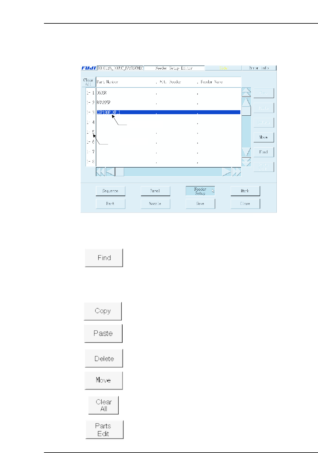
3.4 Editing Feeder Setup Data
(ESR0706e)
The Feeder Setup Editor is used to specify which part is to be set in which slot.
Operation Button Explanations
Searches the feeder setup for a specified character string in the feeder
setup.
The following buttons apply to the line which has been selected in the selection area at
the left side of the screen.
Copies the selected line to the clipboard.
Pastes the clipboard data below the selected line.
Deletes the selected line.
Moves feeder positions, and exchanges feeders.
Cancels all selections.
Edits (at part editor screen) the part to be placed at the selected line.
2 0, F, -99.59, 0.00, 0,
Data input line
Selecting area
XP2S2163Ea
Part 3 Chapter 3 Editor
Edition 2.0 3-3-13 XP-142E System Reference
Setting Item Explanations
Selection Area (Stage-slot No.)
Displays the stage-slot number.
If the feeder skip setting in sequence data is set to [1], then the stage-slot number is
displayed in red.
Part Number
Specifies the part name. No more than 30 characters may be used in the name.
Next Slot No.
This setting specifies the next slot to be used in supplying parts. This setting prevents
frequent machine stops due to parts-out conditions by specifying in advance another slot
(next slot) from which the same part type can be supplied.
Note: In order to use this function, a loop type setting must be specified as shown below.
Note: A “next slot” setting which includes two different stages is not possible.
(Ex.) 1-14
→
2-15
→
1-14
Feeder Name (Presently not supported)
Specifies the name of the feeder to be used. This feeder name may contain no more than
20 characters.
Comment
A feeder comment can be entered, using up to 30 characters. The stage and slot numbers
display together with the comment when an error occurs during production.
(Example) 1-14 → 1-15 → 1-16 → 1-14
XP2S2164E
Part Number Next Slot No.
AAA
AAA
AAA
15
16
14
1-14
1-15
1-16
Part 3 Chapter 3 Editor
Edition 2.0 3-3-14 XP-142E System Reference