XP-142E System Reference-SYS-XP142-2.0E.pdf.pdf - 第169页
Setting Item Explanations Selection Area (Stage-slot No.) Displays the stage-slot number. If the feeder skip setting in sequence data is set to [1], then the stage-slot number is displayed in red. Part Number Specifies t…
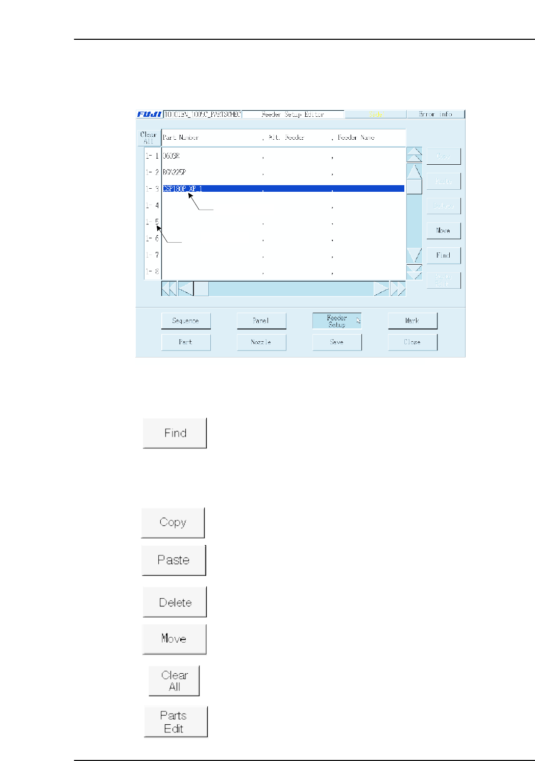
3.4 Editing Feeder Setup Data
(ESR0706e)
The Feeder Setup Editor is used to specify which part is to be set in which slot.
Operation Button Explanations
Searches the feeder setup for a specified character string in the feeder
setup.
The following buttons apply to the line which has been selected in the selection area at
the left side of the screen.
Copies the selected line to the clipboard.
Pastes the clipboard data below the selected line.
Deletes the selected line.
Moves feeder positions, and exchanges feeders.
Cancels all selections.
Edits (at part editor screen) the part to be placed at the selected line.
2 0, F, -99.59, 0.00, 0,
Data input line
Selecting area
XP2S2163Ea
Part 3 Chapter 3 Editor
Edition 2.0 3-3-13 XP-142E System Reference
Setting Item Explanations
Selection Area (Stage-slot No.)
Displays the stage-slot number.
If the feeder skip setting in sequence data is set to [1], then the stage-slot number is
displayed in red.
Part Number
Specifies the part name. No more than 30 characters may be used in the name.
Next Slot No.
This setting specifies the next slot to be used in supplying parts. This setting prevents
frequent machine stops due to parts-out conditions by specifying in advance another slot
(next slot) from which the same part type can be supplied.
Note: In order to use this function, a loop type setting must be specified as shown below.
Note: A “next slot” setting which includes two different stages is not possible.
(Ex.) 1-14
→
2-15
→
1-14
Feeder Name (Presently not supported)
Specifies the name of the feeder to be used. This feeder name may contain no more than
20 characters.
Comment
A feeder comment can be entered, using up to 30 characters. The stage and slot numbers
display together with the comment when an error occurs during production.
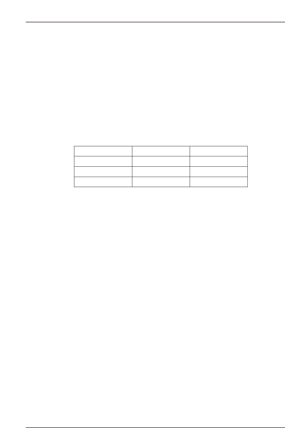
(Example) 1-14 → 1-15 → 1-16 → 1-14
XP2S2164E
Part Number Next Slot No.
AAA
AAA
AAA
15
16
14
1-14
1-15
1-16
Part 3 Chapter 3 Editor
Edition 2.0 3-3-14 XP-142E System Reference
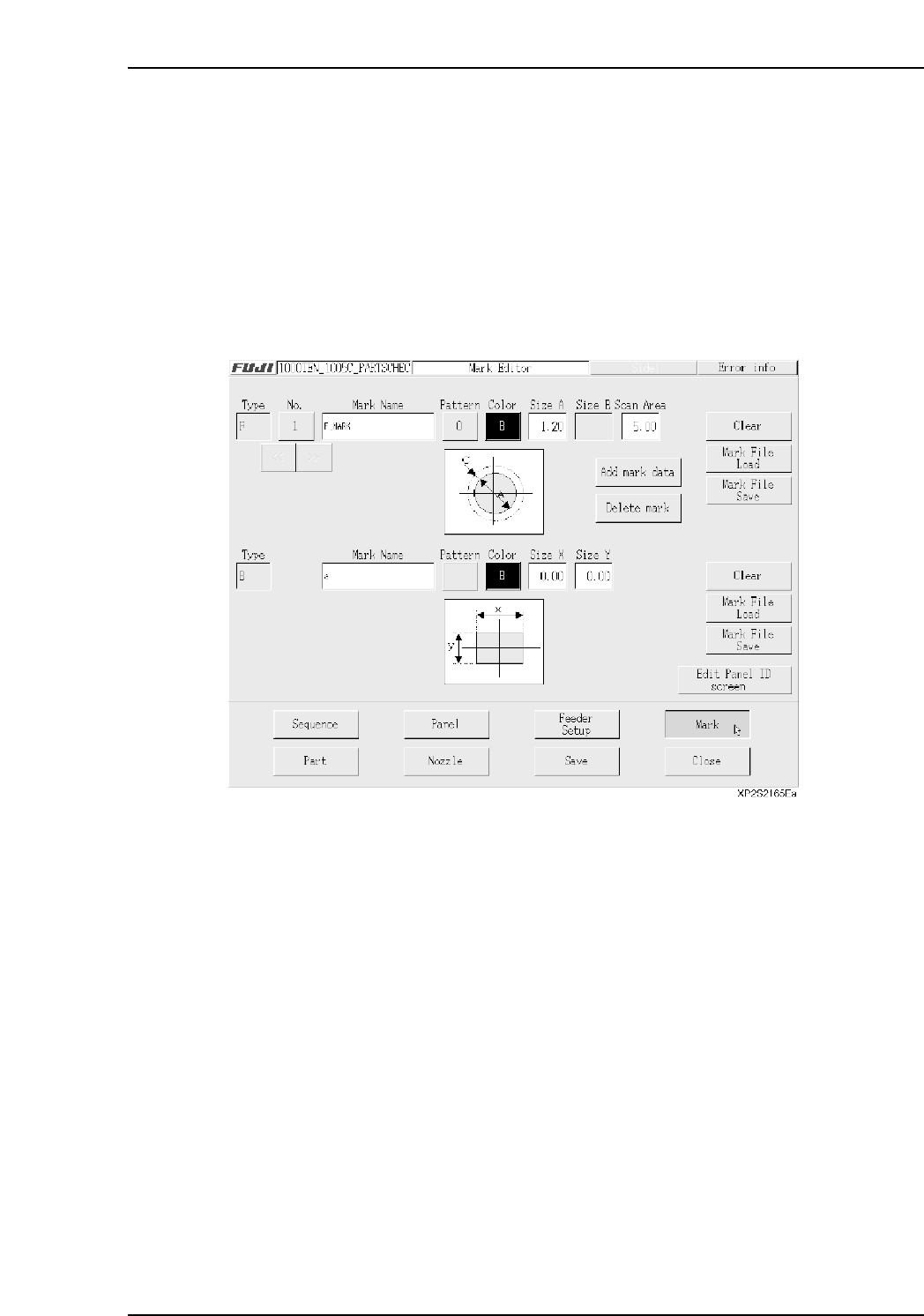
3.5 Mark Editing
(ESR0707c)
This editor is used to measure the various mark types.
The Mark Editor consists of “Fiducial Mark Editor” and “Panel ID (2D Code) Editor”
screens. As the editor items vary according to the mark type, the required items must be
specified. Mark data settings can be saved and read, and registered data can be reused.
Up to 16 mark data can be registered.
3.5.1 Fiducial Mark Editor Screen
The upper part of this screen is the fiducial mark editing area for correcting placing
coordinates, and the lower part is the board skip mark editing area.
<Fiducial Mark Editing Area>
• [No.] button
Indicates the fiducial mark number. Press this button to display the fiducial mark list
screen. (Refer to “■ Fiducial Mark Editor Screen”).
Note: This number is used only at the mark editor screen. It is not registered in the
production program.
• [Mark Name] textbox
Enter the mark name in this textbox. (Max. 23 characters)
Note: The following characters cannot be used in the mark name: (:¥/;*?”<>|). Also, a tilde (~)
cannot be used as the first character of the name.
• [Pattern] button
Press to display the shape graphic where the mark shape can be selected.
• [Color] button
Press to select the mark color.
W: white
B: black
Part 3 Chapter 3 Editor
Edition 2.0 3-3-15 XP-142E System Reference