XP-142E System Reference-SYS-XP142-2.0E.pdf.pdf - 第199页
Notes: Part 3 Chapter 4 Expander Edition 2.0 3-4-4 XP-142E System Reference
Expander Sample
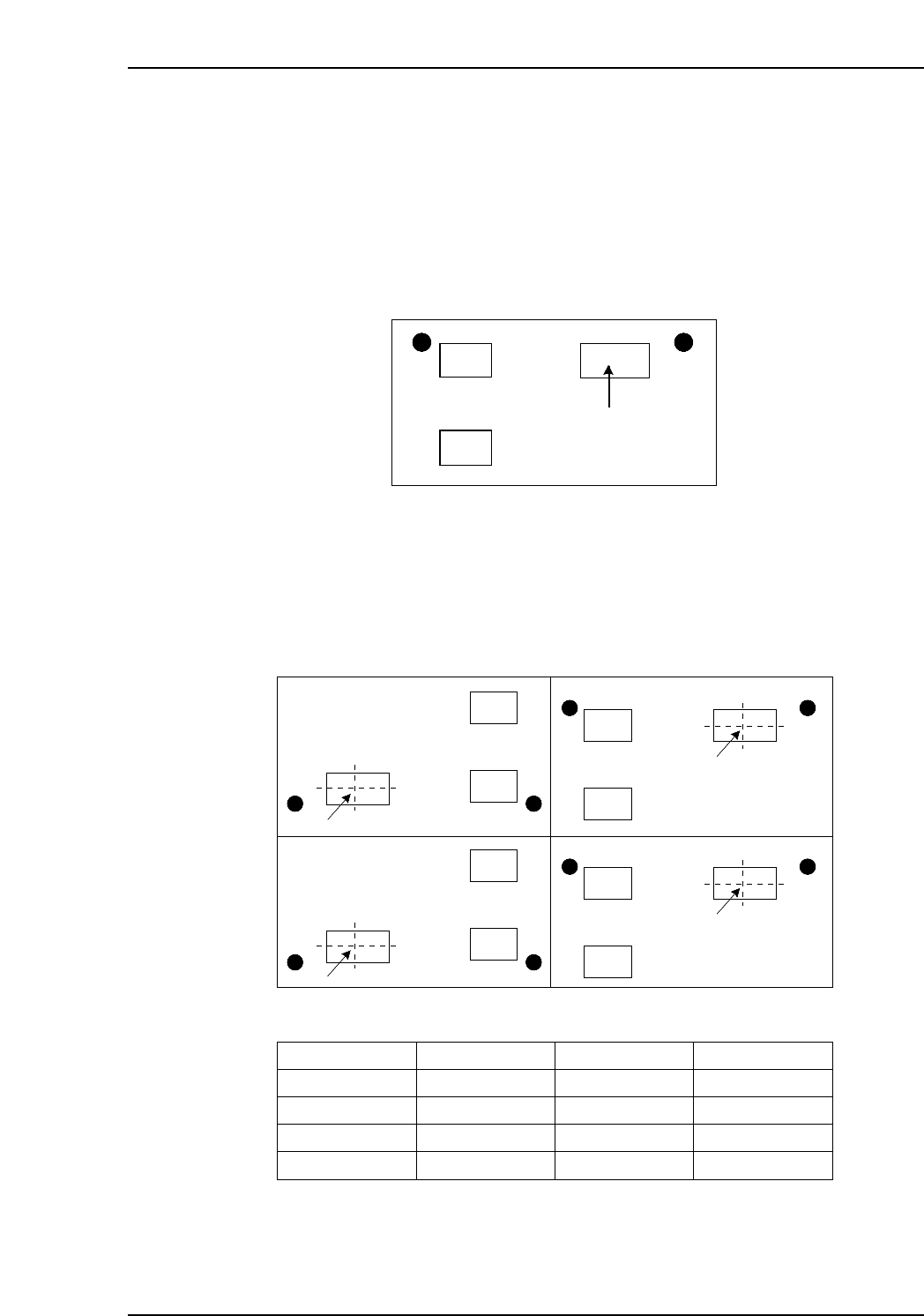
In the sample below, the program is expanded to create a panel which contains four
boards.
1. Determine the part which is to the reference part. If the example below, the upper
right part is the reference part.
2. Determine the position of the reference part on each board. Also determine the
offset angle.
Board 1: Specify the distance (Offset X, Offset Y) from the origin to the reference
part. The offset rotation for the first board must always be “0”.
Board 2: Specify the distance (Offset X, Offset Y) from the origin to the same part.
Board 3, 4: Specify the distance (Offset X, Offset Y) from the origin to the same part.
Moreover, because these two boards are rotated 180 degrees, the offset
rotation must be specified as “180”.
Board 4 Board 2
Board 3 Board 1
(-250, 150)
(-50, 230)
(-50, 100)
(-250, 20)
Reference position
Panel is rotated 180 degrees. Panel is in the same direction.
Board No.
1
2
3
4
Offset X
-50.00
-50.00
-250.00
-250.00
Offset Y
100.00
230.00
20.00
150.00
Offset Rotation
0.00
0.00
180.00
180.00
XP2S2194E
Reference part
XP2S2058E
Part 3 Chapter 4 Expander
Edition 2.0 3-4-3 XP-142E System Reference

Notes:
Part 3 Chapter 4 Expander
Edition 2.0 3-4-4 XP-142E System Reference

Part 4
Creating Templates
at the Machine
(Vision Type 18)
(ESR08AA)
This part explains the procedures for
creating vision processing templates
on XP-series machines.
1. Overview . . . . . . . . . . . . . . . . . . . . . . . . . .4-1-1
2. Creating a Template From Existing Part Data
. . . . . . . . . . . . . . . . . . . . . . . . . . . . . . . . . .4-2-1