XP-142E System Reference-SYS-XP142-2.0E.pdf.pdf - 第193页
Part 3 Chapter 3 Editor Edition 2.0 3-3-38 XP-142E System Reference 3.7 Nozzle Editing (ESR0709d) This editor is used to edit nozzle assignments. Operation Button Explanations Press to perform batch reading of the machin…
Part 3 Chapter 3 Editor
Edition 2.0 3-3-37 XP-142E System Reference
Setting Item Explanations
Packaging Name
Specifies the packaging name. No more than 30 characters may be used in this name.
Note: The following characters may not be used in file names: ( : \ / ; * ? “ < > | ) Also, characters
(˜ .) may not be used at the beginning of the file names.
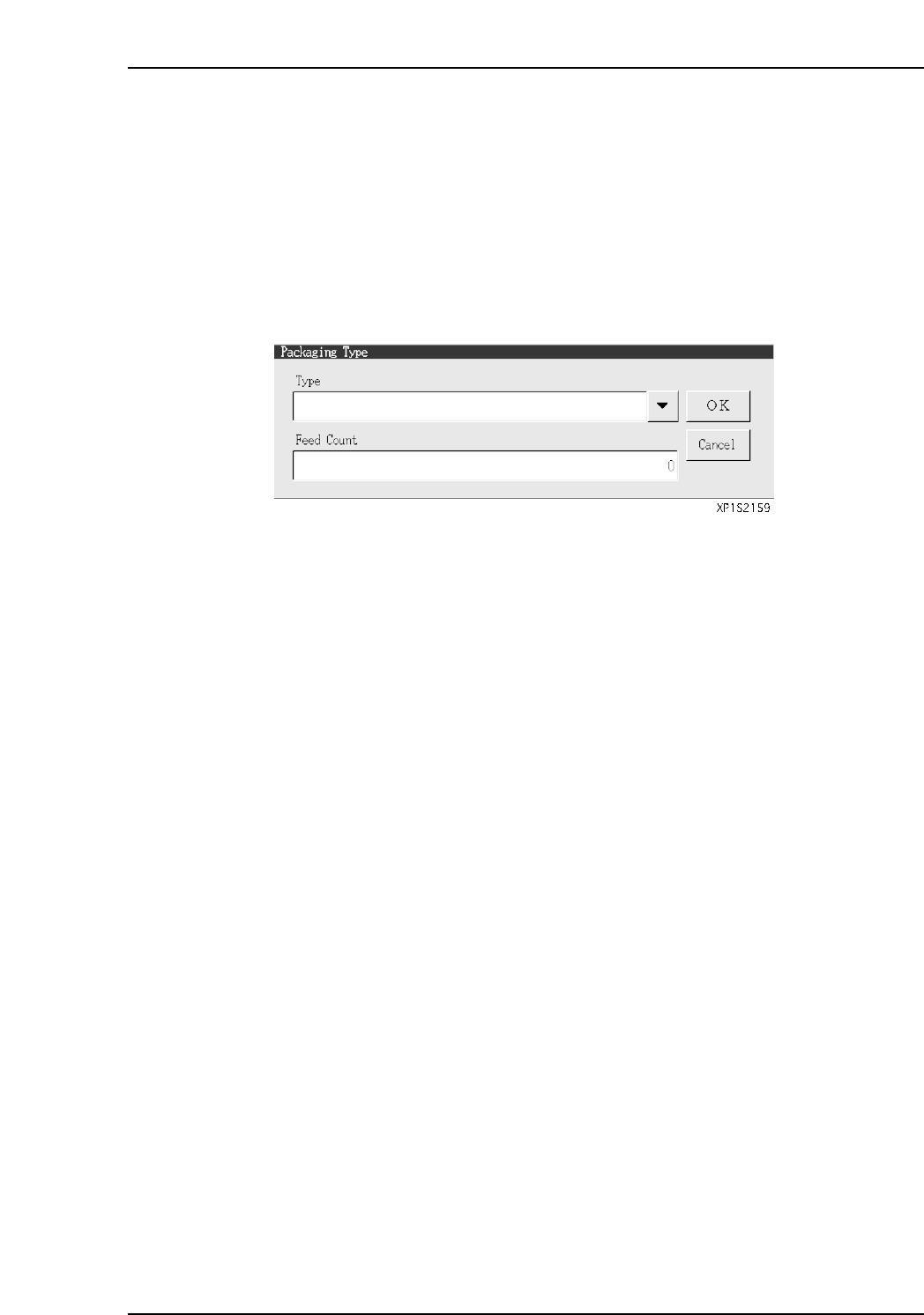
Packaging Type
Click in this field to display the window shown below. Click the [▼] button at this
window, then select the desired part supply method (packaging type) from the drop-
down list. Specify a “Feed Count” (part feed count) setting.
Tape Width
Specifies the tape width. (0 mm ~ 255 mm)
Feed Pitch
Specifies the tape feed distance. (2 mm ~ 100 mm)
Part 3 Chapter 3 Editor
Edition 2.0 3-3-38 XP-142E System Reference
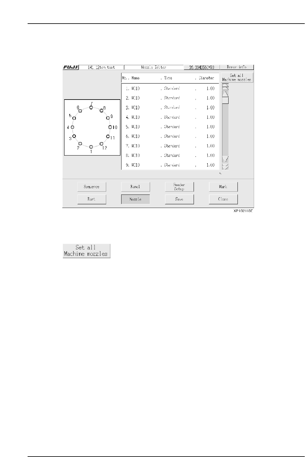
3.7 Nozzle Editing
(ESR0709d)
This editor is used to edit nozzle assignments.
Operation Button Explanations
Press to perform batch reading of the machine’s nozzle information.
When performing a batch input, verify that all the required
production program nozzles are present.
Setting Item Explanations
No.
Specifies the number of the nozzle station.
Name
Specifies the nozzle name.
Type
Specifies the nozzle type. (Standard: standard nozzles, Custom: special nozzles)
Diameter
Specifies diameter of the nozzle. (unit: mm)
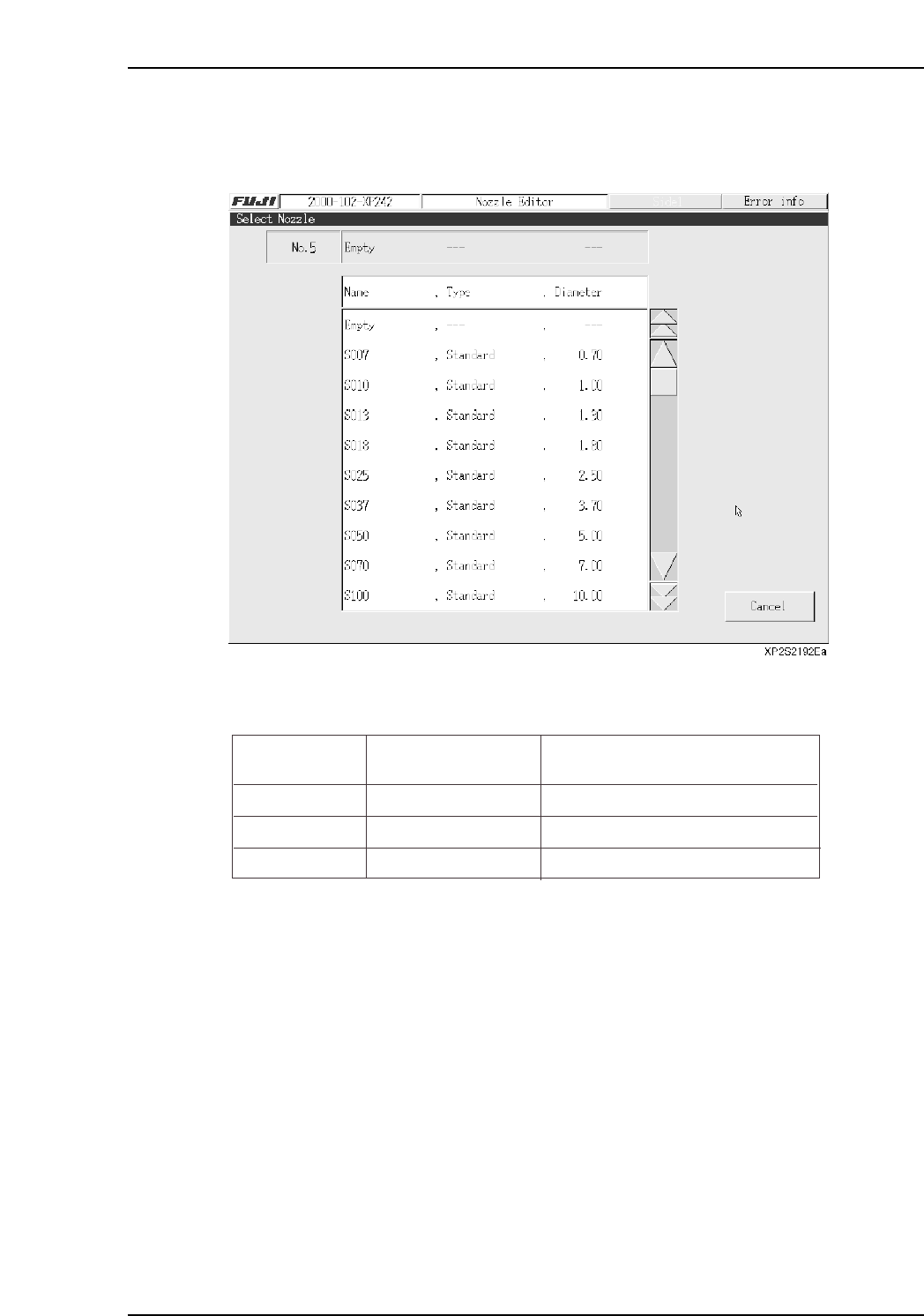
To perform editing, press the number of the nozzle station where editing is desired, then
select 1 nozzle from the nozzle selection screen which then displays. Continue in the
same manner to edit nozzles in other nozzle stations.
The nozzle position where pickup is possible varies according to the part size. Edit the
data so that the pickup nozzle is positioned correctly.
Notes:
1. The part size includes the leads.
2. This applies when the “Direction”, “Pickup Point Offset X,Y”, and “Scan Area X,Y” items are
all set to “0”.
3. The nozzle “Name” appears as “Empty” when no nozzle selection is made.
Name
Max. Part Size
Nozzle Positions Where Pickup
is Possible
Small parts
Medium parts
Large parts
5.00 X 6.20 (mm)
10.00 X 10.00 (mm)
20.00 X 20.00 (mm)
1, 2, 3, 4, 5, 6, 7, 8, 9, 10, 11, 12
1, 4, 7, 10
4, 10
XP1S2156E
Part 3 Chapter 3 Editor
Edition 2.0 3-3-39 XP-142E System Reference