XP-142E System Reference-SYS-XP142-2.0E.pdf.pdf - 第59页
Part 2 Chapter 3 Changeover Edition 2.0 2-3-5 XP-142E System Reference 3.2 Retracting the Head (ESR0216b) The head can be retracted to its retract position using the procedure described below. Procedure 1. At the [Main] …

Part 2 Chapter 3 Changeover
Edition 2.0 2-3-4 XP-142E System Reference
3.1.3 Receiving MCS-2 Programs
(ESR0227h)
The XP can receive production programs from an MCS-2 host system through an RS-
232C interface. The MCS-2 cable can be connected at the DATA PORT at the bottom
right of the rear of the machine.
Procedure
1. Prepare a CP-6(M), CP-642(M), or a CP-643(M) production program at the MCS-2
host.
The machine can be artificially recognized by the MCS-2 host as a CP-6(M),
CP-642(M), or a CP-643(M).
Note: Because the machine has only two MFU units (100 slots / 8 mm tape width
conversion), feeder setup data which exceeds this capacity must not be used. For
details regarding programming and line settings performed at the MCS-2 host, refer
to the manual dealing with that subject.
2. At the [Main] screen, press [Program] then [MCS-2 Program Download].
3. Transmit the production program from the MCS-2 host.
Data Compatibility
Certain data generated on MCS-2 is not compatible with the XP. When the incompatible
data listed below is transmitted, the values are input as 0. This data must be edited at the
machine for these programs to be used.
Data exists at MCS-2 but cannot be transmitted.
• Tape Width (TAPEWIDTH)
Data does not exist at MCS-2.
• Soft Pick speed (PENFCSPN)
Rear side of the XP-142E MCS-2
XP1S2172E
Part 2 Chapter 3 Changeover
Edition 2.0 2-3-5 XP-142E System Reference
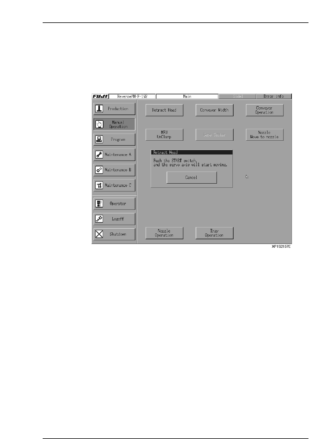
3.2 Retracting the Head
(ESR0216b)
The head can be retracted to its retract position using the procedure described below.
Procedure
1. At the [Main] screen, press [Manual Operation] then [Retract Head].
2. Press START to move the head to its retract position.
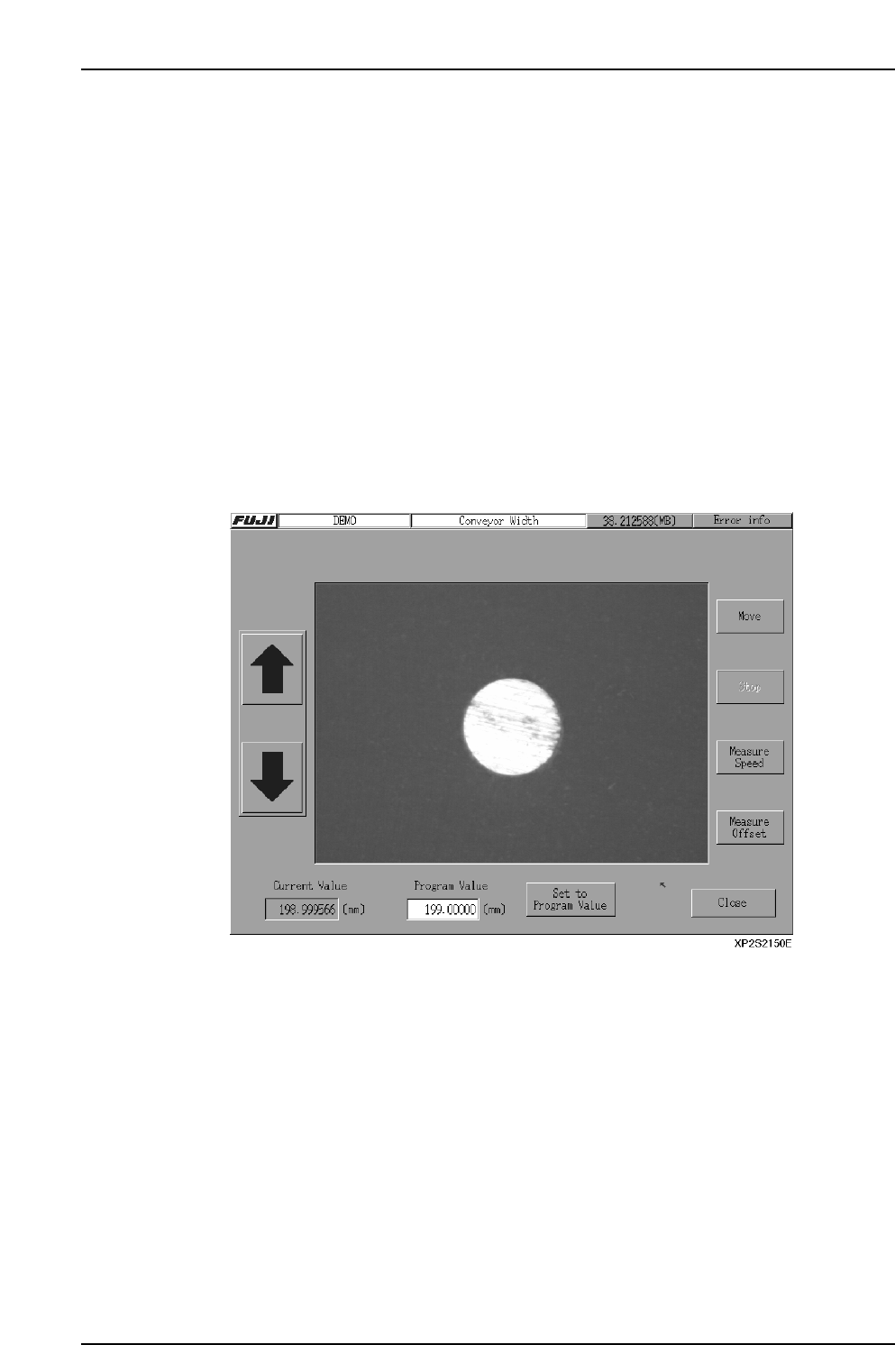
3.3 Adjusting the Conveyor Width
(ESR0217a)
The XP is equipped with a motor-driven conveyor width adjustment system that adjusts
the conveyor width in accordance with the data in the production program being used.
Procedure
1. At the [Main] screen, press [Manual Operation] then [Conveyor Width] to display
the [Conveyor Width] screen.
2. If a production program has already been read, the current conveyor width for
that program displays at the “Program Value” item. To change this value, select
the “Program Value” item to display a numeric keypad, then enter the desired
width value. To return to the production program width value, press [Set to
Program Value].
3. Press [Move] to display a start confirmation dialog box. Press [Start] to change the
conveyor width to the specified value.
4. Press [OK].
5. Press [Close] to return to the [Main] screen.
Note: Prior to performing conveyor width adjustment, ensure that the back-up pins are not located
in a position likely to result in interference with the conveyor. After adjusting the conveyor
width, ensure that the back-up pins are not located below the adjustable rail.
When performing conveyor width adjustment, ensure that no panels exist at any position
other than the In-station or Main-station panel arrival confirmation sensors.
3.3.1 Automatic Conveyor Width Start
The conveyor width is automatically adjusted when automatic operation begins if the
“_AutoConvWidth” Proper data item is set to “1”.
Start Conditions
1. The operation mode must be either “Production” or “Pass”.
2. The new conveyor width must differ by 0.3 mm or more from that specified in the
previous production program.
3. There must be no panels on the conveyor. (If a panel is present on the conveyor,
the width adjustment occurs after panel unloading.)
Part 2 Chapter 3 Changeover
Edition 2.0 2-3-6 XP-142E System Reference