XP-142E System Reference-SYS-XP142-2.0E.pdf.pdf - 第219页
[Angle] button When this button is pressed, a seek line which is perpendicular to the edge can be set. As only single seek lines can be generated by the automatic angle generation function, a single line will be generate…
Center Line Display
When on, the editing image center lines (cross-hairs) display in red.
File Import
Loads a *.tpl file which can then be edited.
When the [File Import] button is pressed, a file selection window displays.
Select the desired file, then press [Open] to edit the template stored in that
file. Data which was being edited before the file was opened is abandoned.
Press [Cancel] to close the file selection window and return to the editing
screen.
Close
Ends the editing operation.
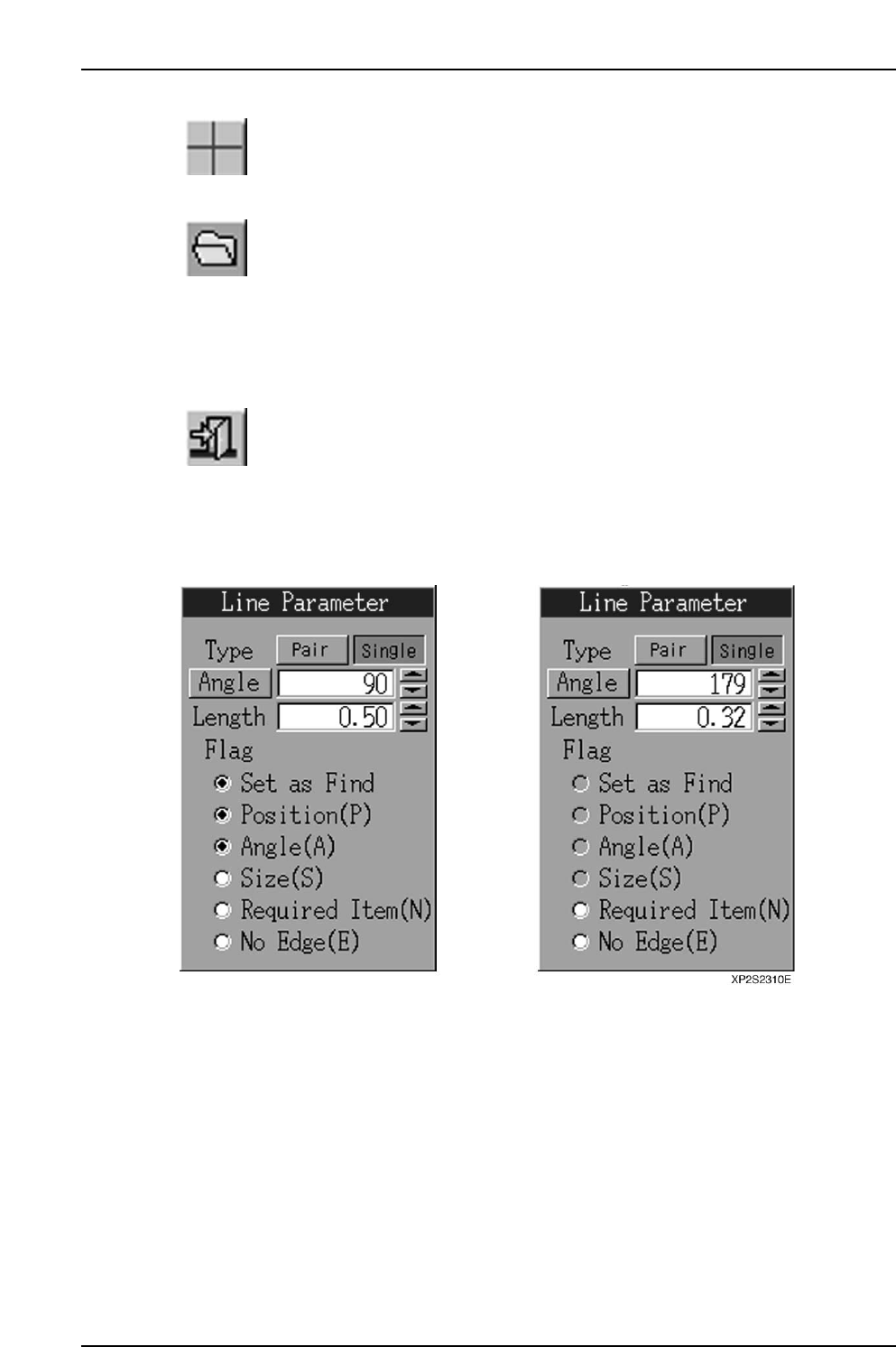
Line parameters examples are given below.
(A) For position lines (B) For inspection lines
[Type] Button
Sets the seek line type (Pair/Single).
Part 4 Chapter 2 Creating a Template From Existing Part Data
Edition 2.0 4-2-16 XP-142E System Reference

[Angle] button
When this button is pressed, a seek line which is perpendicular to the edge can be set.
As only single seek lines can be generated by the automatic angle generation function, a
single line will be generated even if "Pair" is selected at the [Type] button.
[Angle] edit box
Specify the seek line angle here within a -360 ~ 360 range. The setting is specified in
"degree" units. If a value outside the -360 ~ 360 range is entered, a "Setting range
violation" error message displays, and the value cannot be changed.
Angle Increase/Decrease buttons ([▲] [▼])
Press these buttons to increase/decrease the seek line angle in 1-degree increments
within the -360 ~ 360 range.
[Length] edit box
A seek line length of 0.01 or more must be entered. The setting is specified in [mm]
units. The setting range is 0 ~ half the edit screen's diagonal line length. If a setting of
"0" is entered, an error message ("0 length line cannot be set") displays, and the value
cannot be changed. If a setting which exceeds the maximum value is entered, a "Line
which exceeds the current scale maximum cannot be set" error message displays, and the
value cannot be changed.
Length Increase/Decrease buttons ([▲] [▼])
Press these buttons to increase/decrease the seek line length in 0.01mm units within the
"0 ~ half the edit screen's diagonal line length" setting range.
Flag
Checks the flag* on/off status.
* Flag descriptions:
Set as Find … Find/Measure setting.
Position (P) … Accuracy calculation of position data at vision processing.
Angle (A) … Accuracy calculation of angle data at vision processing.
Size (S) … Size correction at vision processing.
Required Item (N) … Ensure a pattern match by setting a seek line that does not "Fail"
vision processing.
No Edge (E) … Set a "no edge" seek line that passes vision processing.
The flag settings are as follows:
(1) Inspection lines can only have "No Edge" and "Required Item" settings.
(2) If "No Edge" is selected, the [Set as Find], [Position (P)], [Angle (A)], and [Size (S)]
flag selections are canceled.
(3) If any one of the [Position (P)], [Angle (A)], or [Size (S)] flags is selected while the
[No Edge (E)] flag is selected, the [No Edge (E)] flag selection is canceled.
(4) The [Set as Find] flag cannot be selected while the [No Edge (E)] flag is selected.
The [No Edge (E)] flag selection must first be canceled before selecting the [Set as
Find] flag.
Part 4 Chapter 2 Creating a Template From Existing Part Data
Edition 2.0 4-2-17 XP-142E System Reference

Notes:
Part 4 Chapter 2 Creating a Template From Existing Part Data
Edition 2.0 4-2-18 XP-142E System Reference