XP-142E System Reference-SYS-XP142-2.0E.pdf.pdf - 第190页
Threshold Offset Binary vision processing occurs if a setting other than “ 0 ” is specified. The recommended setting range is 5 ~ 20. This function is useful for performing vision processing only on the outer shape of pa…

Part 3 Chapter 3 Editor
Edition 2.0 3-3-34 XP-142E System Reference
Vision
Vision Type
Select the Vision Type which corresponds to the part shape, as shown below. Although
data setting conditions are indicated, they do not represent the vision processing
performance, or guaranteed ranges.
Note: Using automatically generated templates for parts with Vision Types other than 18 will not
necessarily eliminate all vision processing errors. If an error occurs, select Vision Type 18,
manually create a template file, and verify that vision processing is performed correctly.
This should eliminate the error and enable the machine to place the part. Refer to Part 4
“Vision Processing” of this manual, or to the MS Algorithm Vision Processing Reference
manual for assistance in creating a manual template.
10: Rectangular chip
18: Other (On XP-142E machines, “18” is the only “other” alternative to the 10, 20,
100, 124, 180 settings)
20: Small outline transistors
100: QFP & Connector (Parts and having at least 1 element consisting of at least 5
leads with a minimum lead pitch of 0.3mm. Maximum number of leads per
element: 128: Maximum number of elements: 128.
124: J-lead parts
180: Aluminum electrolytic capacitor
Camera Position (Presently not supported)
Selects the camera to be used for part vision processing.
Auto: The camera nearest to the part supply stage is used. The Side 1 camera is
used for parts picked up at stage 1, and the Side 2 camera is used for parts
picked up at stage 2.
Front: The Side 1 camera is used.
Rear: The Side 2 camera is used.
Scan Area X
Specifies the vision processing range. When set to “0”, the scan area is automatically
calculated based on the part size. Set a Scan Area X (and Scan Area Y) range which fully
covers the part. (0.00 mm ~ 24.00 mm)
Scan Area Y
Specifies the vision processing range. When set to “0”, the scan area is automatically
calculated based on the part size. Set a Scan Area Y (and Scan Area X) range which fully
covers the part. (0.00 mm ~ 24.00 mm)
Refer to the “Nozzle Allocation Table” in the above item.
Nozzle Allocation Table
Nozzle position Max. scan area
2, 3, 5, 6,
8, 9, 11, 12
5.62 x 6.82 (mm)
1, 7
4, 10
11 x 11 (mm)
25 x 24 (mm)
XP1S2158E

Threshold Offset
Binary vision processing occurs if a setting other than “0” is specified. The
recommended setting range is 5 ~ 20. This function is useful for performing vision
processing only on the outer shape of parts with complex interiors. (0 ~ 255).
Note: This function cannot be used for parts having part data Vision Type settings of 10, 130, and
230.
Gain of Contrast Offset
This setting is used to offset the image contrast. If the image is dull, this setting value
can be increased to increase the recognition rate at vision processing. When set to “0”,
the original image contrast is used. (0 ~ 255). (Default value: 1.0)
Part 3 Chapter 3 Editor
Edition 2.0 3-3-35 XP-142E System Reference
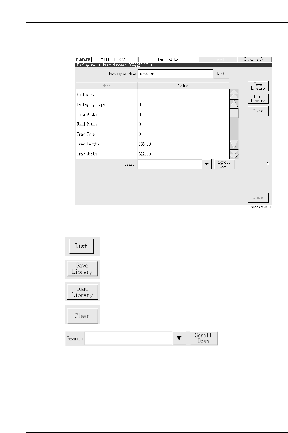
3.6.2 Packaging Editing
This editor is used to specify part supply related settings for feeders, etc.
Operation Button Explanations
Displays a list of packaging types for the parts used in the production
program which has been opened in the editor.
After a confirmation message, the package data is saved to the library.
Loads package data which is saved in the library.
Clears the specified data.
Item searches display the specified data name. Press the black arrow-mark key to
display a classification list. A search can also be performed by entering the data name
directly from the keyboard. Press the [Scroll Down] key to execute a search in the “top to
bottom” direction.
Part 3 Chapter 3 Editor
Edition 2.0 3-3-36 XP-142E System Reference