XP-142E System Reference-SYS-XP142-2.0E.pdf.pdf - 第218页
Center Line Display When on, the editing image center lines (cross-hairs) display in red. File Import Loads a *.tpl file which can then be edited. When the [File Import] button is pressed, a file selection window display…
Image Zoom-out
To zoom-out, click the screen at the center of the desired zoom-out area. With each click,
the zoom-out factor is halved until the original zoom factor is reached. If the zoom-out
image extends beyond the boundaries of the original image, the zoom-out center is
automatically adjusted so that the boundaries are not violated.
Original Image Display
Restores the original image zoom factor when the display has been enlarged
(zoom-in).
Edge Position Correction
An edge position correction can be performed in the [Auto Find Set] ‡ [Edge
Position Correction] sequence.
An edge position correction can be performed on both inspection and
position seek lines regardless of the display mode.
Multiple measurement points display for lines where the edge was detected,
and the edge position correction was successful. (The number of multiple
measurement points is fixed at 5.)
Each of these operations are explained below.
Auto Find Set
If no Find seek lines have been set, the "Find Set" function is automatically executed.
Edge Position Correction
The line edge position is detected, and the seek line center is adjusted so that it is aligned
with the edge position.
The operation ends in failure if the line edge is not found, and an error message displays.
The failed line displays in a cyan color from the point immediately after the edge
position correction until the error message window is closed, and multiple measurement
points do not display.
When the edge position correction fails, the "Image position correction" "Template
generation completed" functions cannot be performed.
Image Position Correction
Performs vision processing, and the image center position and angle are
corrected using pair seek lines. This function is disabled if no pair lines are
set.
The screen's center position is corrected and re-displayed.
To correct the image, the editing image center and angle are corrected so that
the recognized workpiece is positioned at the center of the image. Moreover,
single seek lines are also corrected by the same amount as the image center
and angle. The coordinates and angles of pair seek lines remain unchanged,
and are not corrected. After all other corrections have been completed, an
edge position correction is performed.
Part 4 Chapter 2 Creating a Template From Existing Part Data
Edition 2.0 4-2-15 XP-142E System Reference
Center Line Display
When on, the editing image center lines (cross-hairs) display in red.
File Import
Loads a *.tpl file which can then be edited.
When the [File Import] button is pressed, a file selection window displays.
Select the desired file, then press [Open] to edit the template stored in that
file. Data which was being edited before the file was opened is abandoned.
Press [Cancel] to close the file selection window and return to the editing
screen.
Close
Ends the editing operation.
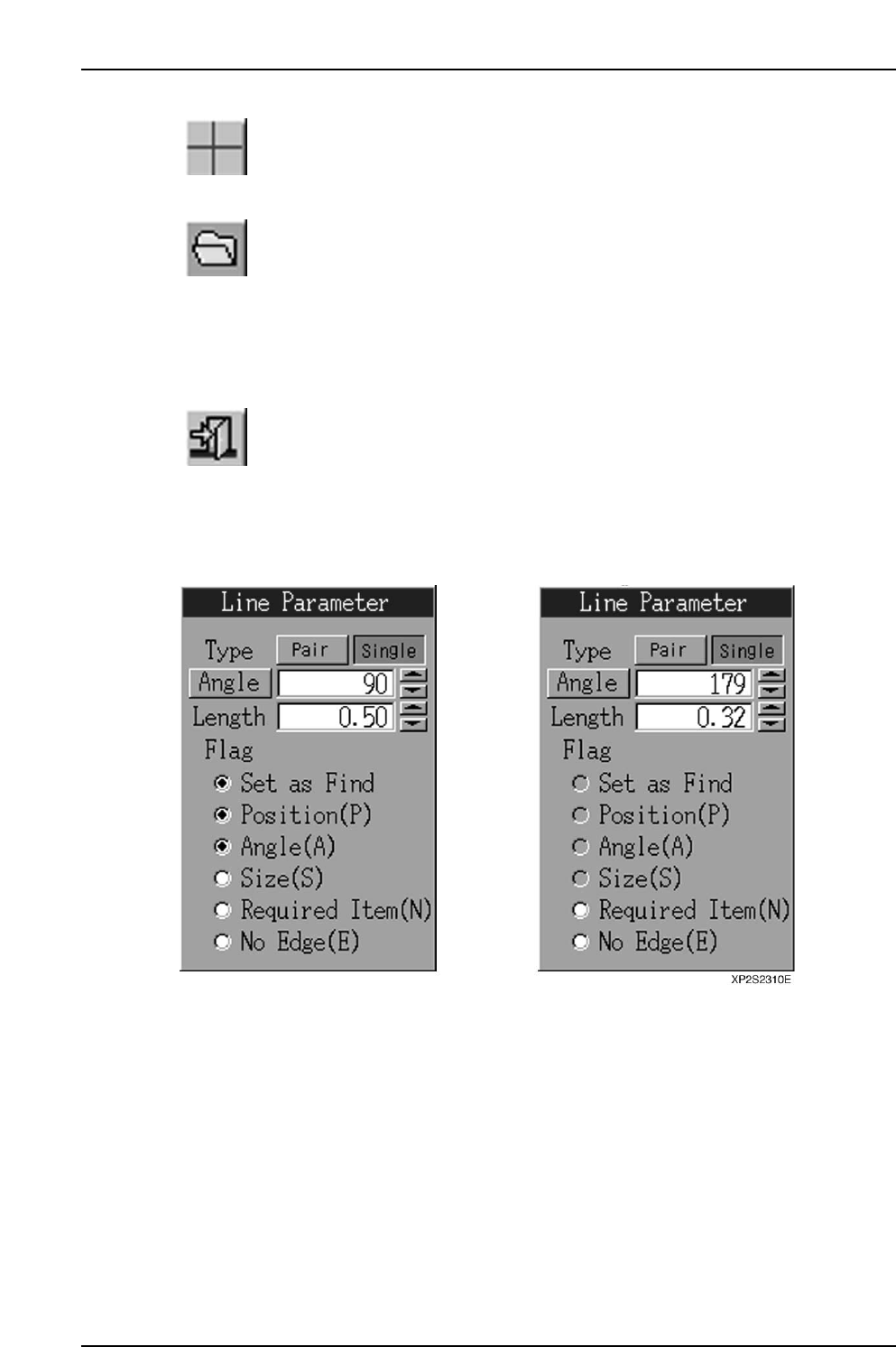
Line parameters examples are given below.
(A) For position lines (B) For inspection lines
[Type] Button
Sets the seek line type (Pair/Single).
Part 4 Chapter 2 Creating a Template From Existing Part Data
Edition 2.0 4-2-16 XP-142E System Reference

[Angle] button
When this button is pressed, a seek line which is perpendicular to the edge can be set.
As only single seek lines can be generated by the automatic angle generation function, a
single line will be generated even if "Pair" is selected at the [Type] button.
[Angle] edit box
Specify the seek line angle here within a -360 ~ 360 range. The setting is specified in
"degree" units. If a value outside the -360 ~ 360 range is entered, a "Setting range
violation" error message displays, and the value cannot be changed.
Angle Increase/Decrease buttons ([▲] [▼])
Press these buttons to increase/decrease the seek line angle in 1-degree increments
within the -360 ~ 360 range.
[Length] edit box
A seek line length of 0.01 or more must be entered. The setting is specified in [mm]
units. The setting range is 0 ~ half the edit screen's diagonal line length. If a setting of
"0" is entered, an error message ("0 length line cannot be set") displays, and the value
cannot be changed. If a setting which exceeds the maximum value is entered, a "Line
which exceeds the current scale maximum cannot be set" error message displays, and the
value cannot be changed.
Length Increase/Decrease buttons ([▲] [▼])
Press these buttons to increase/decrease the seek line length in 0.01mm units within the
"0 ~ half the edit screen's diagonal line length" setting range.
Flag
Checks the flag* on/off status.
* Flag descriptions:
Set as Find … Find/Measure setting.
Position (P) … Accuracy calculation of position data at vision processing.
Angle (A) … Accuracy calculation of angle data at vision processing.
Size (S) … Size correction at vision processing.
Required Item (N) … Ensure a pattern match by setting a seek line that does not "Fail"
vision processing.
No Edge (E) … Set a "no edge" seek line that passes vision processing.
The flag settings are as follows:
(1) Inspection lines can only have "No Edge" and "Required Item" settings.
(2) If "No Edge" is selected, the [Set as Find], [Position (P)], [Angle (A)], and [Size (S)]
flag selections are canceled.
(3) If any one of the [Position (P)], [Angle (A)], or [Size (S)] flags is selected while the
[No Edge (E)] flag is selected, the [No Edge (E)] flag selection is canceled.
(4) The [Set as Find] flag cannot be selected while the [No Edge (E)] flag is selected.
The [No Edge (E)] flag selection must first be canceled before selecting the [Set as
Find] flag.
Part 4 Chapter 2 Creating a Template From Existing Part Data
Edition 2.0 4-2-17 XP-142E System Reference