XP-142E System Reference-SYS-XP142-2.0E.pdf.pdf - 第32页
1. Machine Overview (ESR0104) 1.1 Machine Controls The machine uses a combination of a touch screen and conventional push buttons. The function of each of the buttons on the machine is detailed below. START This button i…

1. Machine Overview . . . . . . . . . . . . . . . . . . .1-1-1
1.1 Machine Controls . . . . . . . . . . . . . . . . . . .1-1-1
1.2 Touch Screen . . . . . . . . . . . . . . . . . . . . . .1-1-3
2. Glossary . . . . . . . . . . . . . . . . . . . . . . . . . .1-2-1
Part 1
General
(ESR01AA)
This part provides usage of the
machine control panel, and includes
a list of the terminology used in this
manual.
1. Machine Overview
(ESR0104)
1.1 Machine Controls
The machine uses a combination of a touch screen and conventional push buttons. The
function of each of the buttons on the machine is detailed below.
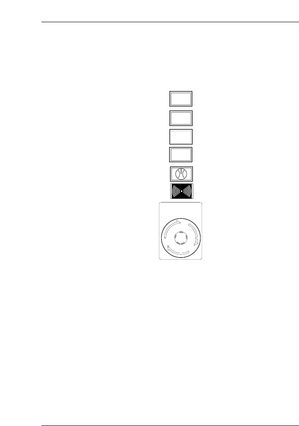
START
This button is pushed to commence operation. This button can only be pushed when the
machine is in START ready status (i.e., when the button is flashing).
READY ON
This button cancels an error status and resupplies the 200V power to the servo system.
CYCLE STOP
This button can be used during operation to stop the machine at the end of the current
movement. Unlike the EMERGENCY STOP button, pressing CYCLE STOP does not cut
the 200V power. Or, when the operation mode is Pause, the temporary interruption of
production is possible.
SYSTEM ON
This button turns on the power supply to the machine and boots up the control software.
READY
ON
START
SYSTEM
ON
EMERGENCY
STOP
CYCLE
STOP
XP1S1001E
Part 1 Chapter 1 Machine Overview
Edition 2.0 1-1-1 XP-142E System Reference

Side 1/2 ENABLE/LOCK
Toggle this switch to enable operation at the desired side of the machine. It is not
possible to enable operation if the switch at the other side of the machine is set at the
“LOCK” position.
EMERGENCY STOP
Pressing an EMERGENCY STOP button cuts the power source to the machine and stops
operation immediately. This button locks in position when pressed, and must be turned
clockwise to release it.
Users should familiarize themselves with the locations of the EMERGENCY STOP
buttons prior to operating the machine. In addition to the button on the front of the
machine (shown in the figure above), further EMERGENCY STOP buttons are positioned
at the rear of the machine, and on the optional MTU safety fence.
Refer to the illustration in Chapter 5 of the Safety Guidelines to confirm the positions of
all the EMERGENCY STOP buttons.
Part 1 Chapter 1 Machine Overview
Edition 2.0 1-1-2 XP-142E System Reference