KE2010.Instruction Manual.Ver.2.01,Rev.08.pdf - 第121页
4 − 14 Station sel ection (Dat a which can be print ed depending on the model name) Data types which can be printed vary depending on the model of a machine. For a 2010 or 2030 − PW B data − Placement data − Component da…
4 − 13
Text Out, Print and Cancel buttons
Print: starts printing the selected data.
Cancel: closes the dialog box displayed on the screen.
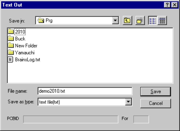
Text Out: Outputs data as text.
When you click the <Text Out> button, the dialog box appears on the
screen as shown in the figure below.
Specify where to save the text and the name on this dialog box.
The default setting in the "Save in" box is the directory/folder under which
the production program file is stored.
Placement data
Select the input order of Placement data.
Component data
Select the Component data window type: Details or List.
Pick data
Select Pick data mode:
− Input order
− Position order
− Feeder setup sheet Excluding comment
− Feeder setup sheet Including comment
4 − 14
Station selection (Data which can be printed depending on the model name)
Data types which can be printed vary depending on the model of a machine.
For a 2010 or 2030
− PWB data
− Placement data
− Component data
− Pick data
For a 2020 or 2040
− PWB data
− Placement data
− Component data
− Pick data
− VIsion data
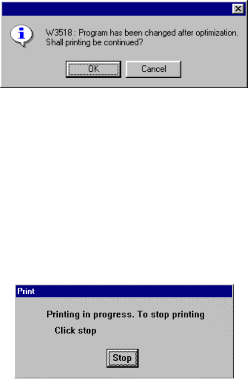
If the following dialog box appears on the screen after printing the selected data, it
indicates that the program data has been modified after you executed the
Optimization utility the last time. Note that the currently displayed data may be
different from the optimized data.
<OK> button: Continues printing data although its contents are different from
those of the optimized file.
<Cancel> button: Terminates printing, then returns to the dialog box previously
displayed on the screen.
When you execute the Optimization utility again, the displayed program data
becomes the same as the newly optimized data, so the dialog box shown above
will not appear on the screen.
After you select a menu or select the <OK> button on the dialog box above, the
following dialog box appears on the screen.
4 − 15
4.2.6.2 Nozzles setup
The permanent nozzle setup, the nozzle setup performed by optimization, and the
number of nozzles are printed out.
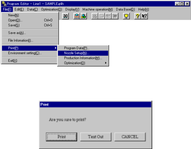
Select “Print (P)”, then “Nozzle Setup (N)” on the File menu as shown below.
When you select the [Nozzle Setup] command, the dialog box appears on the
screen as shown in the figure below.
<Print>: starts printing.
<Text Out>: displays the "Text Out" dialog box on the screen.
<CANCEL>: cancels printing.
When you click the <Print> or <Text Out> button, HLC prints data as shown below:
• Nozzle setup condition
The nozzle numbers and the number of nozzles assigned newly when you
execute optimization are to be printed.
The result varies depending on the setting of “Nozzle” on the “Arrangements”
tab of the “Optimization” dialog box.
• ATC permanent nozzle information
The permanent nozzle setup is to be printed.
• Nozzle setup with optimization
Nozzles newly assigned with optimization are to be printed.
The result varies depending on the setting “Nozzle” on the “Arrangements” tab
of the “Optimization” dialog box.