KE2010.Instruction Manual.Ver.2.01,Rev.08.pdf - 第570页
7 − 33 7.2.2.10. 2 Opti on Device Enable W hen y ou select t he tab “Opt ion Device enable”, the “O ption Device enable” setting dialog box appears on the screen as shown in Figure 7. 2.2.10. 2. Figure 7.2.2. 10.2 “Optio…

7 − 32
(3) Production operation
Table 7.2.2.10.1 Placement when a unit is set as “Unused”
No. Unit Production operation
nozzle 1
nozzle 2
nozzle 3
1 L-Head
nozzle 4
2 R-Head nozzle 1
(Not to be
displayed when
your model is a
KE-2010.)
Components to be placed by these heads are not placed.
The Optimization utility does not assign any component to these
heads.
3 Light The machine does not place a component that is recognized with the
VCS under the penetrative light.
4 L-OCC Placement of components is carried out without BOC mark or bank
mark recognition.
Placement of IC mark components is not carried out.
5 R-OCC
(Not to be displayed when your
model is a KE-2010.)
Placement of components is carried out without bank mark
recognition.
6 Feeder float detector
(Front inside, front outside,
rear inside and rear outside)
This function is disabled but placement of components is carried out.
7 Support plate stopper This function is disabled but placement of components is carried out.
7 − 33
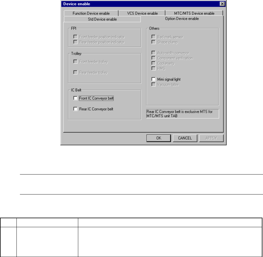
7.2.2.10.2 Option Device Enable
When you select the tab “Option Device enable”, the “Option Device enable”
setting dialog box appears on the screen as shown in Figure 7.2.2.10.2.
Figure 7.2.2.10.2 “Option Device enable” setting dialog box
(Screen example when a KE-2020 is used)
Note: Data displayed under the “Trolley” and “IC belt” menu items of the dialog box
above varies depending on the model you use (see Table 7.2.2.10.2).
(1) Setting items
No. Item Description
1 Option Device enable Unit to be used/not used
When you specify a malfunctioning unit as “a unit not used” on this dialog
box, you can allow the machine to pick up and place a component without
modifying the production program data.
Table 7.2.2.10.2 shows whether a component is actually placed on a board or
not if the production program requires the unit defined as to be used in order
to complete component placement operation.
(2) Setting the unit
− Specify the device unit to be used with the check box.
− A device unit that is not installed as an option (dimmed on the dialog box)
cannot be checked.
− Zeroing is required again when you change the head status from “Not to be
used” to “To be used”.

7 − 34
(3) Production operation
Table 7.2.2.10.2 Placement when a unit is set as “Unused”
No. Unit Production operation
1 Feeder positioning indicator
(front, rear)
This function is disabled but placement of components is carried out.
2 Feeder trolley
(front, rear)
KE2010,2020,2040
(front L, front R, rear L, rear R)
KE2030
This function is disabled but placement of components is carried out.
3 IC Conveyor belt
(front, rear) (Not available for a
KE-2030)
This function is disabled but placement of components is carried out.
4 Bad mark sensor This function is disabled but placement of components is carried out.
5 Shape clamp Offset adjustment of the mark position when mark is used or of the
placement point when mark is not used is not carried out.
Offset adjustment is made by referring to the mark for placement
when mark is used.
6 Auto-width conveyor This function is disabled but placement of components is carried out.
7 Component verification The machine does not perform the component verification function
even though this function is designated.
8 Coplanarity Placement is carried out without performing coplanarity even when
component coplanarity is designated.
9 HMS This function is disabled but placement of components is carried out.
10 Mini signal light This function is disabled but placement of components is carried out.
11 Vacuum table This function is disabled but placement of components is carried out.