KE2010.Instruction Manual.Ver.2.01,Rev.08.pdf - 第696页
10 − 12 (1) Setti ng items No. Item Description 1 Assembling position of head Mounting position of each head view ed from the OCC 2 Assembling angle of LA Mounting angle of the laser alignment onto the main unit (relativ…
10 − 11
10.5 Head Offset
When you select the [Set-up group] command on the menu bar, then the [Head
offset] command on the displayed menu, the following the “Head offset” dialog box
appears on the screen.
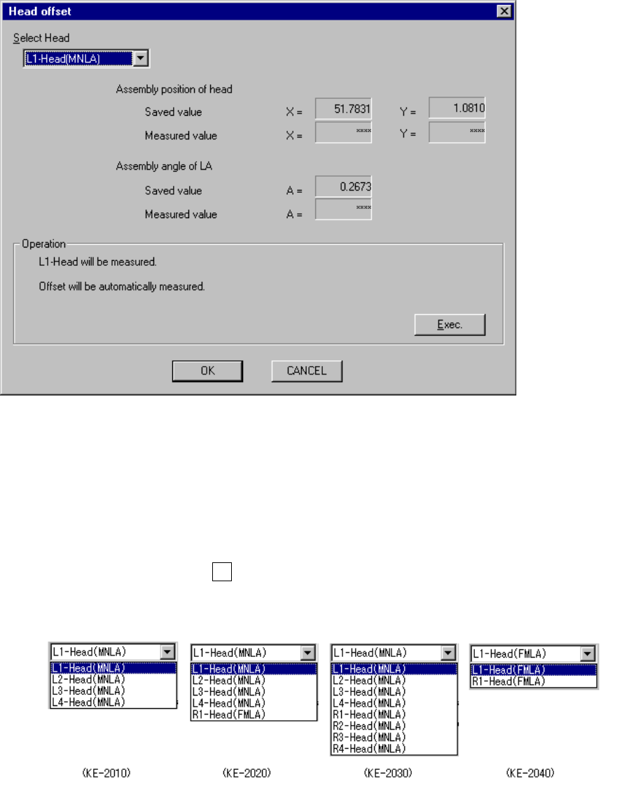
Figure 10.5.1 Head offset screen
− Select Head
Using this combo box, select the head to be set.
The heads which are not checked on the “Device enable” menu invoked from the
Machine Setup menu (that is, checked as “Not used”) cannot be selected.
When you press the Alt key and the down arrow key at the same time, the
following list appears on the screen.
(Assembling angle
already set)
(Assembling angle
measured)
10 − 12
(1) Setting items
No. Item Description
1 Assembling position of head Mounting position of each head viewed from the OCC
2 Assembling angle of LA Mounting angle of the laser alignment onto the main unit (relative to
the main unit) (° )
(2) How to set
− For the head selected in the “Select Head” combo box, follow the instructions
displayed on the dialog box to set the selected head.
− When you click the <OK> button, your setting becomes valid (but not be
saved at this point).
− When you click the <CANCEL> button, your setting becomes invalid.
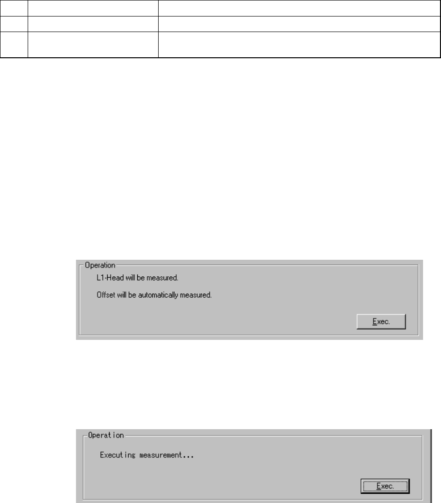
− How to operate
Follow the displayed instructions to obtain the appropriate value automatically.
The machine sets up the head selected with the combo box.
Click the <Exec.> button.
When you click the <Exec.> button, the machine starts measurement.
− Measurement operation
① Attach the No. 508 nozzle onto the selected head.
An error occurs if no nozzle is set for the ATC. In this case, assign the
nozzle on the “ATC nozzle setup” menu invoked from the Machine Setup
menu.
② Move the jig from the jig station to the calibration block if there is no jig on
the calibration block.
An error occurs if the jig cannot be picked up. In this case, remount the
jig.
10 − 13
③ Set the vacuum of the calibration block to ON to pick the jig.
④ Using the OCC, check the position of the jig, and measure the center
position and the inclination of the jig.
An error occurs if two holes of the jig cannot be recognized. In this case,
remount the jig.
⑤ Pick the jig with the selected head, then set the vacuum of the calibration
block to OFF.
⑥ Recognize the jig with the laser alignment unit.
⑦ Calculate the laser alignment unit mounting angle and the head mounting
position based from the inclination of the jig obtained at Step 4 and the
recognition results at Step 6.
⑧ Using the OCC, recognize the calibration block position to calculate its
center position and inclination.
⑨ Mount the jig at the center of the calibration block, then set the vacuum of
the calibration block to ON to pick the jig.
To mount the jig, the machine corrects the inclination of the jig calculated
at Step 4, the laser alignment unit mounting angle and the head mounting
position calculated at Step 7, and the inclination of the calibration block
calculated at Step 8.
⑩ Using the OCC, recognize the position of the jig.
An error occurs if the distance from the jig to the calibration block is 1 mm
or longer (absolute value). In this case, you may have to set the MS
parameters again.
⑪ Repeat steps 4 to 10.
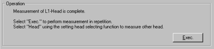
(When the left 1 head is selected)
The machine has finished measurement operation.
To repeat the measurement operation, select the <Exec.> button.
When you select the <Exec.> button, the previous screen reappears.
To measure another head, select the desired head in the “Select Head”
combo box.
When you change the selected head in the “Select Head” combo box, the
initial screen appears.
To quit Self-calibration mode, click the <OK> button.