KE2010.Instruction Manual.Ver.2.01,Rev.08.pdf - 第762页
13 − 6 (2) Pi ping diagram ( Head) Blow-Sw P ø8 (3) Pi ping diagram (O verall changer table, Common t o all four t ables) ø 6 ø 6 ø 6 ø 6 ø 6 ø 6 P Ejector Filter Pressur e sensor No zzle Roller lever Roller lever Select…
13 − 5
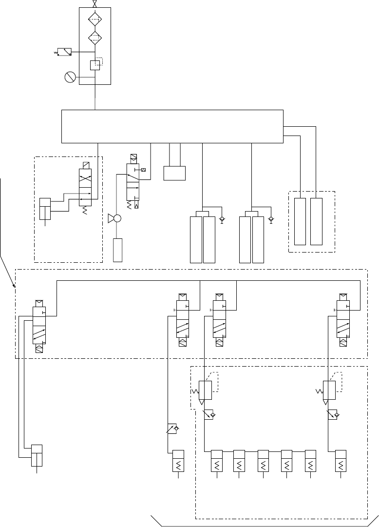
Refer to the following piping diagram.
(1) Piping diagram (Main body)
Cell block
AB
PR
AB
AB
Pusher Y (x5)
Stopper
Electromagnetic valve
manifold
(Option)
Head unit
Connector bracket F
Drive cylinder 20L F
Overall feeder
exchange trolley F
Manifold
Pressure
gauge
Regulator
Pressure
switch
Mist separator
Filter
φ12
Factory
-
piping
(Option)
(Ejector)
CVS
φ6 ST=30
Drive cylinder 20R F
Connector bracket R
Drive cylinder 20L R
Drive cylinder 20R R
φ4
φ4
φ4
φ4
φ4
φ6
φ6
φ6
φ6
φ8
φ8
φ6
φ6
(Option)
Pusher X (x5)
PWB transport
solenoid
Overall feeder
exchange trolley R
(Option)
AE/E valve
AE/E valve
(meterin)
13 − 6
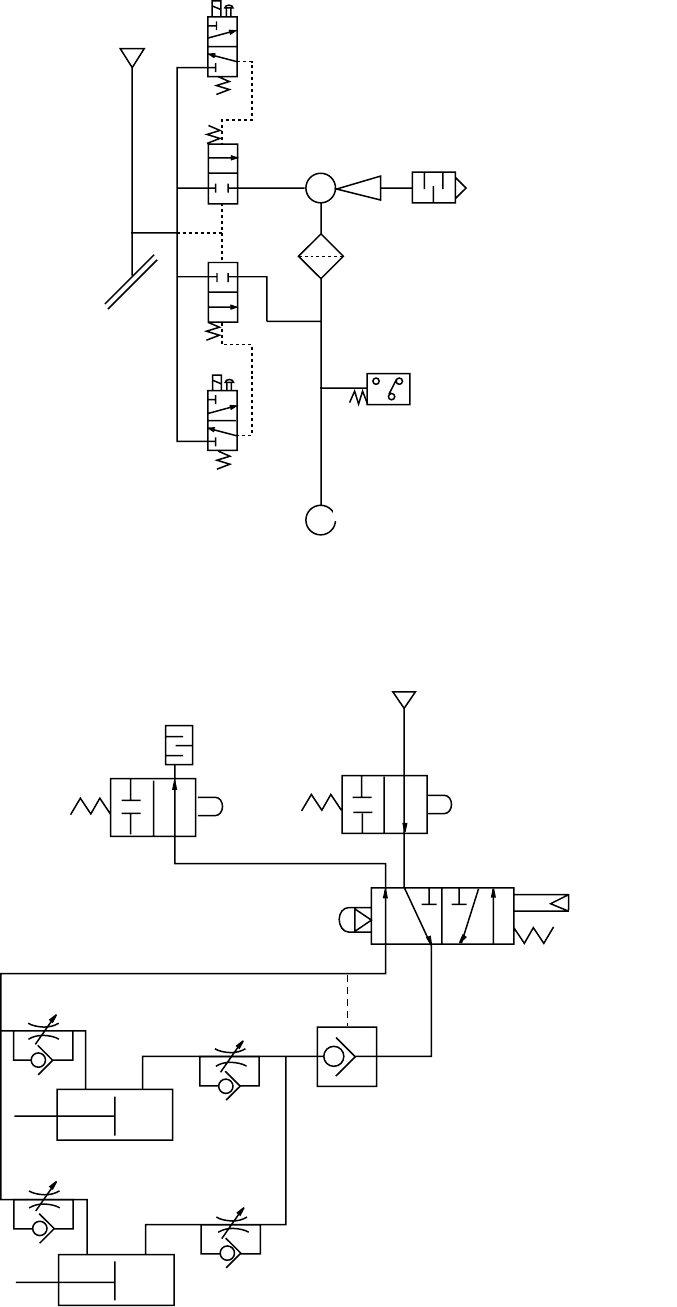
(2) Piping diagram (Head)
Blow-Sw
P
ø8
(3) Piping diagram (Overall changer table, Common to all four tables)
ø6
ø6
ø6
ø6
ø6
ø6
P
Ejector
Filter
Pressure sensor
Nozzle
Roller lever
Roller lever
Selector
Pilot check valve
13 − 7
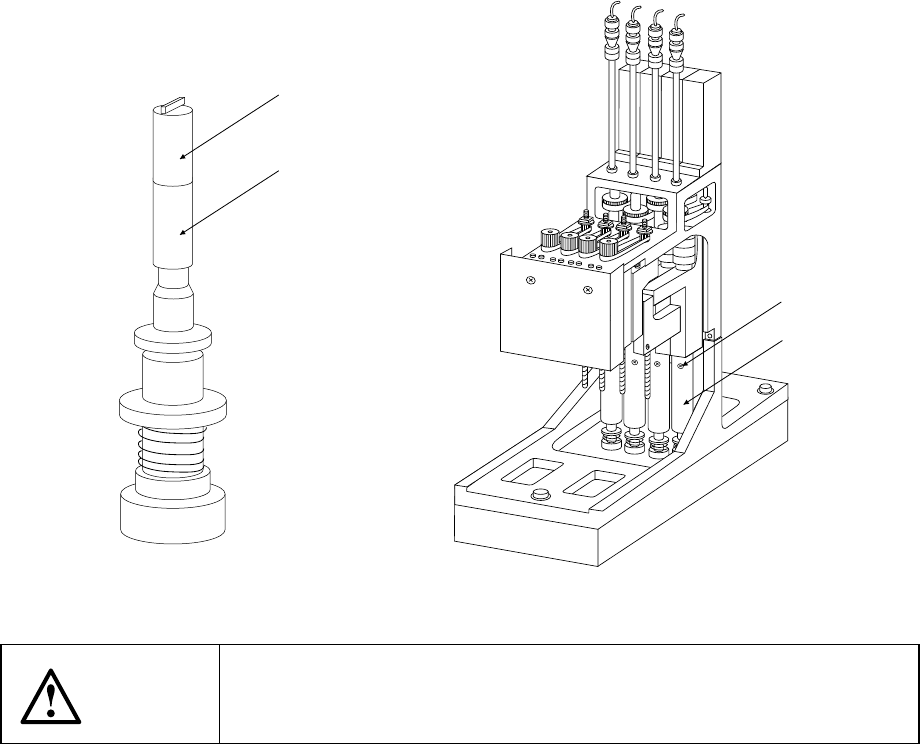
13.2.4 Air filter (Head)
1) Loosen the screw ② fixing the Z slide shaft ① to pull out the nozzle outer shaft
③.
2) Check to see if there is any contamination of the filter ④.
3) If any, remove the filter ④ from the nozzle outer shaft, the replace it with a new
one.
4) Push the nozzle outer shaft ③ into the Z slide shaft ①, then fix it with the screw
②.
Filter ④: Part number E3052729000
WARNING
To prevent the body from injury which can be caused by accidental
activation of the machine, turn off the power of the machine before
following the operation above.
④
③
②
①