KE2010.Instruction Manual.Ver.2.01,Rev.08.pdf - 第743页
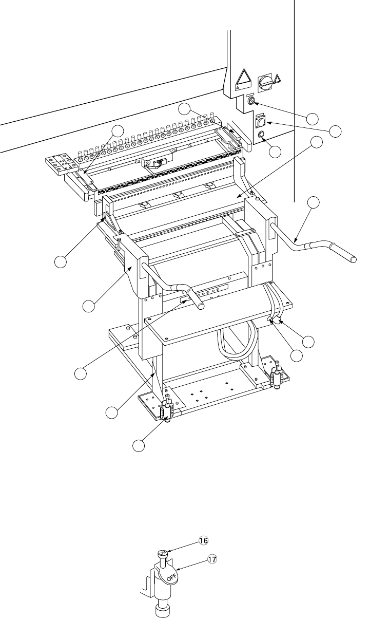
12 − 13 12.9 Replacing Overall feeder exchange trolley 3 9 11 1 5 4 8 7 6 13 15 2 14 12 Figure 12.9.1 Ov erall feeder exchange trolley Figure 12.9. 2 Trolley stopper t ⑯ Lock pedal ⑰ Lock release pedal
12 − 12
12.8 Handling HMS
The HMS (Height Measurement System) is an optional device used to detect the
height of a component such as a feeder pick position.
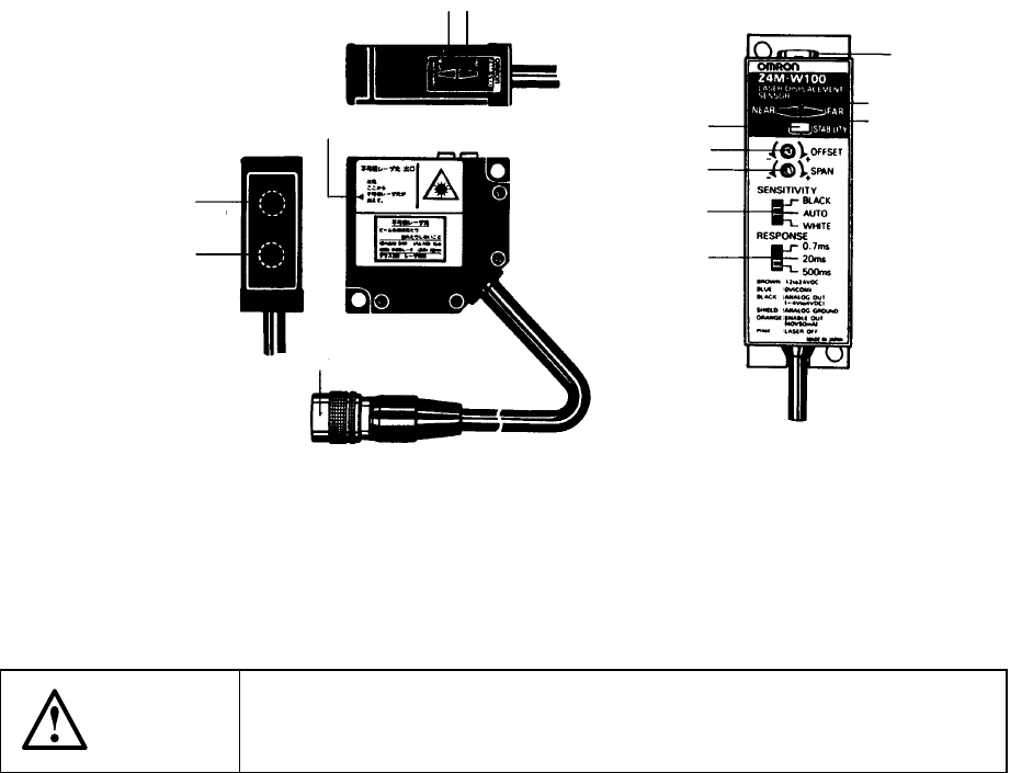
This optional device consists of two parts: the height sensor which is composed of
the sensor and amplifier, and the HMS board which controls the height sensor. To
use this optional device, install it on the head unit.
The amplifier of the height sensor and the controls and switches located on the HMS
board are all already set at the factory. Do not change their settings.
Sensor part Amplifier part
Figure 12.8.1
The HMS conforms to Class 3B Laser Safety Standard of JIS C6802.
It can be used safely when following the instructions described in this manual.
CAUTION
The laser beam used for the high sensor is invisible. Be careful not to
expose you to the beam or do not try to view the beam.
Photo-transmitting section
(laser emitting section)
Photo-receiving section
Connector
Laser emission mark
Ran
g
e indicator
(
NEAR indicator
)
(
FAR indicator
)
STABILITY indicato
r
OFFSET adjustment control
SPAN adjustment control
RESPONSE speed switch
SENSITIVITY switch
(NEAR indicator)
(FAR indicator)
Connector
Range indicator
12 − 13
12.9 Replacing Overall feeder exchange trolley
3
9
11
1
5
4
8
7
6
13
15
2
14
12
Figure 12.9.1 Overall feeder exchange trolley
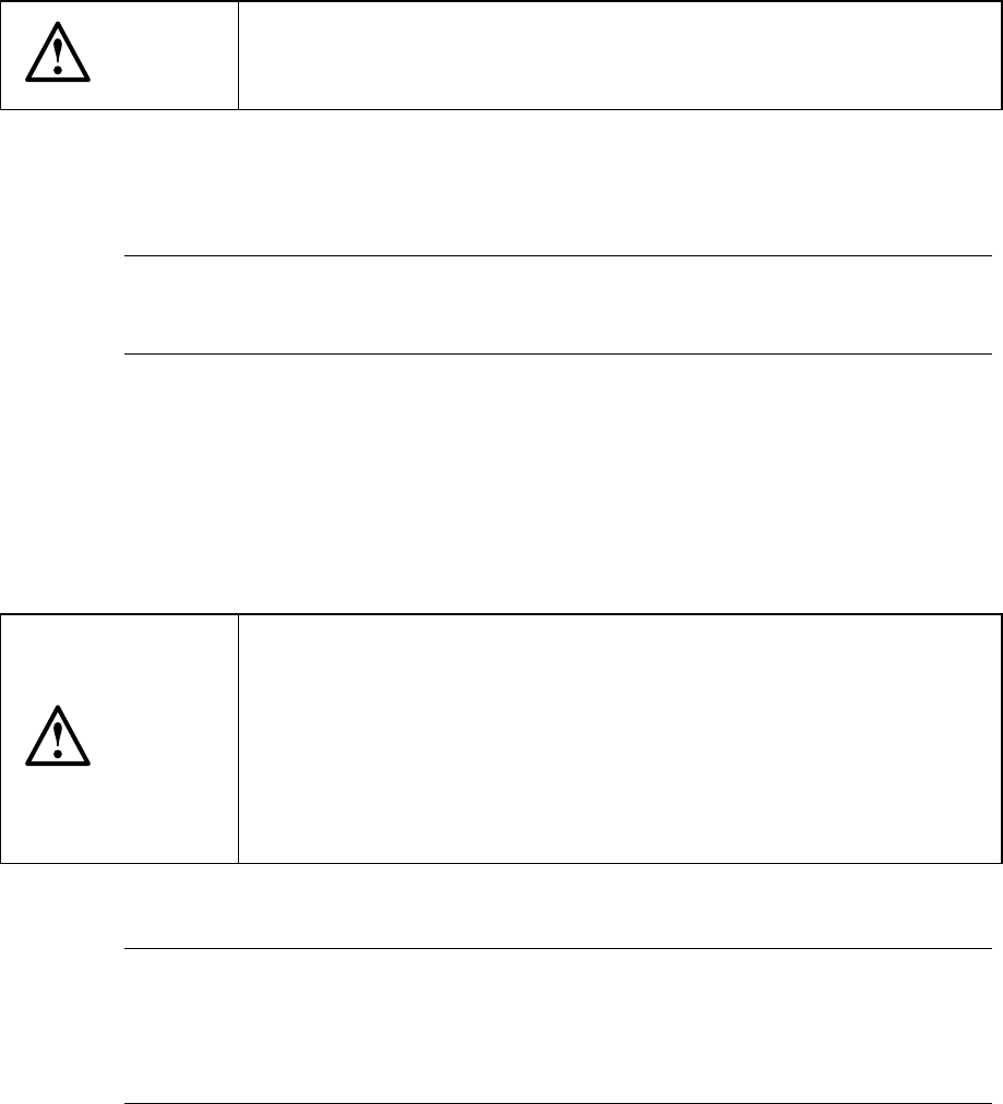
Figure 12.9.2 Trolley stopper t
⑯ Lock pedal
⑰ Lock release pedal
12 − 14
Mounting
1) Install each feeder in the feeder bank ②.
2) Check that the selector ⑥ is set to OFF, and the bank lifter u is set below the
bank stopper ⑧.
3) Insert the overall feeder exchange trolley ① into the chip shooter main unit until
the trolley stopper plate ⑪ touches the bank stopper ⑧.
4) Lock the trolley stoppers ⑤ at the left and right.
5) Set the selector ⑥ to ON. The feeder bank ② goes up and is installed in the
chip shooter main unit.
CAUTION
To avoid any accident caused by sudden activation of the machine,
turn off the power, close the air cock, and release the remaining air
before starting installation.
6) Insert the feeder connector ⑫ into the power supply ⑬ of the cover of the chip
shooter main unit. Then, insert the air coupler ⑭ into the female union ⑮ of
the cover of the chip shooter main unit.
Note: If you operate the machine even though either one of the front and rear
stations of the overall feeder exchange trolley descends, the X and Y
axes move at the lower speed as if the cover is open.
Dismounting
1) Detach the air coupler and the feeder connector from the chip shooter main unit.
2) Set the selector to OFF.
The feeder bank goes down, and it comes off from the chip shooter main unit.
CAUTION
To prevent your body from injury and to avoid damage to the machine,
install the overall feeder exchange trolley only after the machine is
stopped completely.
Do not place your hand in the machine, nor move your face or head
close to the machine when operating the selector.
When operating the selector, be sure to check the selector so that you
cannot operate other switches, especially main power switch by
mistake.
3) Release the lock of the trolley stoppers at the left and right.
Note: If you use the overall feeder exchange trolley to attach the feeder bank
on the main unit of the machine, do not touch the grip
④
of the overall
feeder exchange trolley or do not impose any load on it while the
system is teaching the component pick-up position on each feeder or
while it is producing a PWB.