KE2010.Instruction Manual.Ver.2.01,Rev.08.pdf - 第490页
6 − 1 14 Notes: The item "Ref. pin Adjust" is displayed as it is specif ied on the Operation option menu. You cannot change t his setting. Note that t he placement of fset specif ied on the "PW B productio…
6 − 113
6.5 Trial Run
When you select the [Production conditions] command from the menu bar, then the
[Trial Run] command on the displayed menu, the "Trial Run conditions" screen
appears.
CAUTION
The "Trial run" starts immediately after the <START> switch is pressed.
To avoid a risk of injury, do not place your hand in the machine, nor
move your face or head close to the machine during operation.
Before pressing the <START> switch, check that there is no one who is
working in the machine.
Before pressing the <START> switch, check that there is no one who
can be injured when the head starts to move.
Before pressing the <START> switch, check that there are no obstacles
(tools and jigs) attached or left in the machine.
(1) Setting items
No. Item Description
1 Setting items
selection
Switch the displayed dialog box among the "Production conditions" dialog box,
"Trial run conditions" dialog box, and the "Dry run conditions" dialog box.
2 Trial PWB no. Set the number of boards for trial run.
3 Trial ckt. Set the circuit for trial run. This is not used for single circuit boards. The
following setting can be made.
All ckt.: Components set for trial run are placed for all circuits.
Ref. ckt.: Components set for trial run are placed for reference circuits only.
4 Trial range Set the range for trial run. The following setting can be made.
Spec. place: Only for the placement positions set as Yes for the “trial” field of
the placement data.
Spec cmpnt: Only for the components set as Yes for the “trial” field of the
component data.
All: For all placement positions.
5 Tracking Station Select the unit to be tracked: left, right or both.
6 Placement ofs. Designate offset for all placement positions. This offset is added to the
placement positions for
actual component placement. (Range: ±2.0 mm)
7 Place tracking After trial run of the board, designate whether or not to perform placement
tracking by the camera. If performed, set whether it is manual or automatic.
Off: Placement tracking is not performed.
Automatic: Placement tracking is performed automatically.
Manual: Stops at each placement position, and then goes to the next
placement position through a key-in by the operator.
8 Pick tracking Before trial run of the board, designate whether or not to perform pickup position
tracking by the camera. If performed, set whether it is manual or automatic.
Off: Pickup tracking is not performed.
Automatic: Pickup tracking is performed automatically.
Manual: Stops at each pickup position, and then goes to the next pickup
position through a key-in by the operator.
9 Automatic interval When tracking is performed automatically, designate the stop time duration at a
stop position. (Unit is in 10 ms, and 1 is equivalent to 10 ms.)
6 − 114
Notes: The item "Ref. pin Adjust" is displayed as it is specified on the Operation option
menu. You cannot change this setting.
Note that the placement offset specified on the "PWB production menu" is also
applied to the trial run.
The item "Ref. pin Adjust" is displayed as it is specified on the Operation option
menu. You cannot change this setting.
(2) Operation
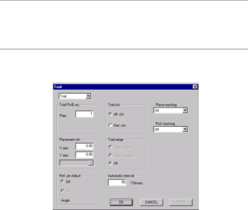
Figure 6.5.1 shows the "Trial" dialog box.
Figure 6.5.1 "Trial" start-up dialog box
①
Setting items selection
Switches the dialog box to be displayed: Production conditions dialog box,
Trial Run dialog box, and Dry Run dialog box.
②
Trial PWB no.
Enter the number of PWBs on which you want to place parts for test.
③
Trial ckt.
Select either "All ckt." or "Ref. ckt." for trial circuits by the radio button.
When the board has only one circuit, you can select any of the circuits.
When "All ckt." is selected for the use of multi-circuit PWBs, parts specified in
the "Trial range" box are placed on all circuits of the PWBs.
When "Ref. ckt." is selected, parts specified in the "Trial range" box are
placed on the reference circuits of the PWBs.
④
Trial range
Select a trial range by the radio button.
Spec. place: Places only components for which "Yes" is specified in "Trial"
field of placement data.
Spec. cmpnt: Places only components for which "Yes" is selected in "Trial"
field of component data.
All: All placement positions entered are subject to operation.
6 − 115
⑤
Tracking Station
Select which station is to be used for tracking a placement operation.
⑥
Placement ofs.
If the boards of a certain lot have a specific offset (during printing process and
reference hole making process), enter here X and Y offsets to apply the
entered offset of the placement positions to the board.
⑦
Place tracking
Using the radio button, set whether or not to perform placement tracking after
trial run by the camera, and also the types of tracking.
⑧
Pick tracking
Using the radio button, set whether or not to perform pickup tracking before
trial run by the camera, and also the types of tracking.
⑨
Automatic interval
Enter the time interval of automatic run in the edition box. (Input value: 1 to
500)
6.5.1 Starting the trial run
To start the trial run, press the <START> switch after setting the trial run conditions.
The green signal lamp lights to indicate that the production is in progress.
6.5.2 Display of the production status
When the <START> switch is pressed and production starts, the status of the
production (the same as that of the board production) appears on the screen.
For details, see section "Display of the production status" of the "PWB production".
The Operations of the Pause, Stop, and Exit commands in the execution of the test
production are the same as those of the board production.
6.5.3 Monitoring by camera
(1) Automatic run
When "Automatic" is selected in the "Place tracking" field, the placement monitor
camera moves over a trial placement position after trial run, shoots the
component placed circuit and outputs the result to the monitor screen.
The camera stops over the point for a time period set by the item "Automatic
interval", then goes to the next point of placement to be monitored.
For a part whose length or width is specified longer than 5.00 mm in component
data, the camera moves to the four corners of the component.