KE2010.Instruction Manual.Ver.2.01,Rev.08.pdf - 第699页
10 − 15 (2) How to se t − Follow the instructions displayed on the dialog box above to set the VCS selected in the “Select VCS” combo box. − W hen you click t he <OK> butt on, your setting s become valid (but not b…
10 − 14
10.6 VCS Offset (Not Available with a KE-2010)
When you select the [Set-up group] command on the menu bar, then the [VCS offset]
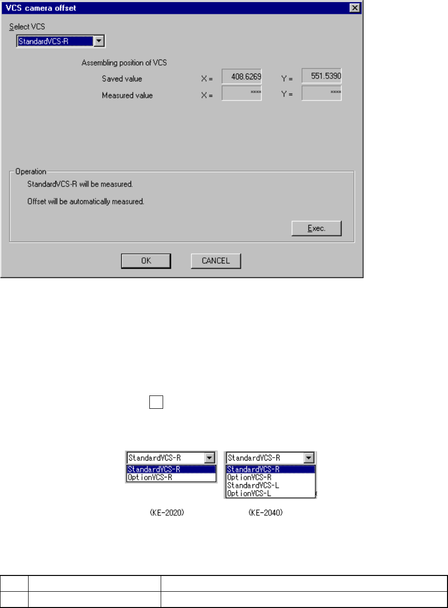
command on the displayed menu, the following “VCS camera offset” dialog box
appears on the screen.
Figure 10.6.1 “VCS camera offset” dialog box
− VCS setting
Select the VCS to be set in the “Select VCS” combo box.
You cannot select any unit which is not checked (that is, “not used”) on the “Device
enable” menu invoked from the Machine Setup menu.
When you press the Alt key and the down arrow key at the same time, the
following list appears on the screen.
(1) Setting items
No. Item Description
1 Assembling position of VCS Each VCS assembling position
(Assembling position
already set)
(Assembling position
measured)
10 − 15
(2) How to set
− Follow the instructions displayed on the dialog box above to set the VCS
selected in the “Select VCS” combo box.
− When you click the <OK> button, your settings become valid (but not be
saved at this point).
− When you click the <CANCEL> button, your settings become invalid.
− How to operate
Follow the instructions displayed on the screen. The appropriate value is
automatically obtained.
(When the right standard VCS is selected)
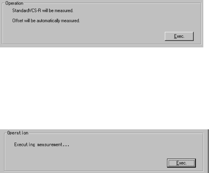
The machine sets up the VCS selected in the “Select VCS” combo box.
Select the <Exec.> button.
When you select the <Exec.> button, the machine moves the selected head
along the theta axis in from 0 to 15-degree units 24 times repeatedly to obtain
the average value.
− Measurement operation
① Attach the No. 508 nozzle onto the FMLA head.
An error occurs if the nozzle is set for the ATC. In this case, assign the
nozzle on the “ATC nozzle setup” menu invoked from the Machine Setup
menu.
② The FMLA head picks up the jig from the jig station.
③ Move the FMLA head to the position where the selected VCS camera
recognizes.
④ The machine recognizes the jig position with the VCS to measure the
center position of the jig.
10 − 16
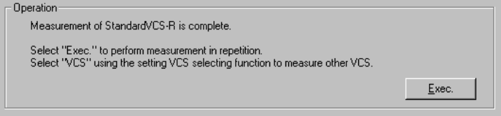
(When the right standard VCS is selected)
The machine has finished measurement operation.
To repeat the measurement operation, select the <Exec.> button.
When you select the <Exec.> button, the previous screen appears.
To measure another VCS, select the desired VCS in the “Select VCS” combo
box.
When you change the VCS to be set in the “Select VCS” combo box, the
initial screen appears.
To quit Self-calibration mode, select the <OK> button.