KE2010.Instruction Manual.Ver.2.01,Rev.08.pdf - 第798页
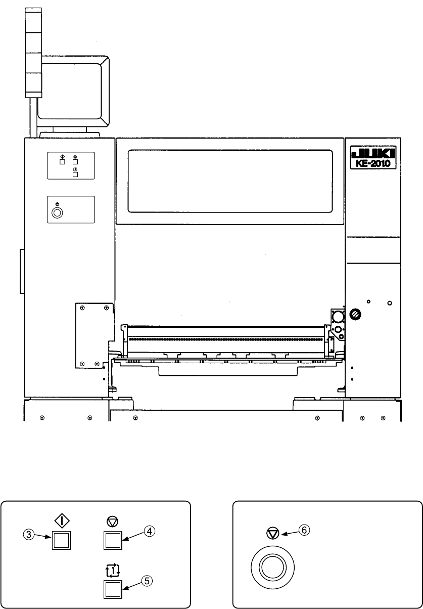
5 <Rear view> Figure 2.3 Figure 2.4 Figure 2.5
4
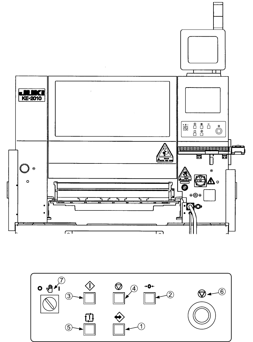
2. Other push button switches
<Front view>
Figure 2.1
Figure 2.2
5
<Rear view>
Figure 2.3
Figure 2.4 Figure 2.5
6
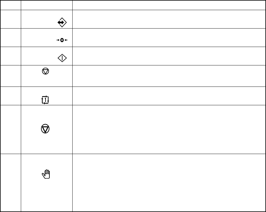
Table 2.1.6.1
No. Switch Function
1
ONLINE Use to allow the machine to connect to the HLC (enter the online status).
The switch lights up when the machine enters Online mode.
2
ORIGIN
Use to zero all the axes.
3
START
Use to start an actual or false production run
4
(PAUSE, STOP)
Use to stop an actual or false production run. Press the switch once to put
the production run in a pause status. Press the switch the second time to
stop the production run.
5
SINGLE CYCLE Use to stop the production run when one board has been produced.
Press the switch a second time to exit from this status.
6
Emergency
Use to bring the machine to an immediate stop if the machine malfunctions
or there could be an imminent personal injury.
When the switch is pressed, it brings the motor and other drive mechanisms
to an immediate stop and turns ON the red lamp of the signal tower.
To reset the switch, turn it in the direction of the arrow.
Do not use this switch for the purposes other than emergency stops.
7
Maintenance When an operator opens the safety cover, normally the control over the
safety parts such as the motor power supply is turned off. When you set
the Maintenance switch (key-type switch) to ON (from 0 to 1), the system
enters Maintenance mode.
0 (OFF): Production mode (normal)
1 (ON): Maintenance mode
(Note that only an administrator who owns the maintenance key should set
the Maintenance key to ON.)