KE2010.Instruction Manual.Ver.2.01,Rev.08.pdf - 第426页
6 − 50 Error content s No. Display (Cause of the error) 1 No components 2 Different component type 3 LA retry over 4 Retry over 5 Off line 6 Supply 7 Operation error 8 Laser recognition error 9 Chip rise 10 Transfer mist…
6 − 49
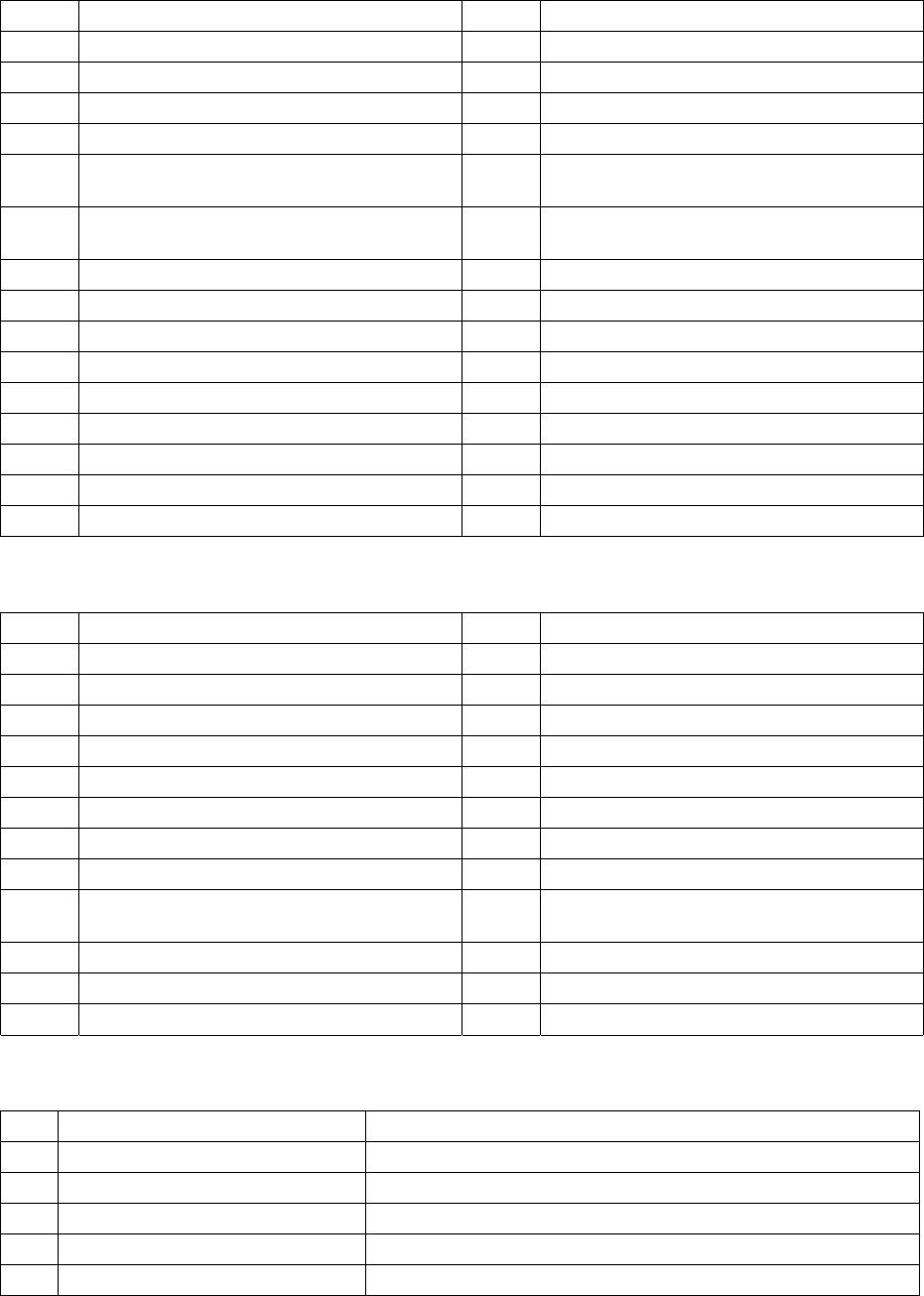
Value Error contents Value Error contents
235 IPC Object Close Error (DTS-1) 302 Retry over
236 IPC Object Close Error (DTS-2) 303 No component
241 IPC Send Error (MTC-1) 304 Offline
242 IPC Receive Error (MTC-1) 305 Supply
243 IPC Send Error (MTC-2) 402 Time Out (Ready Waiting Observation
10sec)
244 IPC Receive Error (MTC-2) 403 Time Out (Sync Character Observation
4sec)
245 IPC Send Error (MTS-1) 404 Time Out (ETX Observation 3sec)
246 IPC Receive Error (MTS-1) 405 MTS Power Off
247 IPC Send Error (MTS-2) 406 Time Out (Responseless Observation 60sec)
248 IPC Receive Error (MTS-2) 407 Receive Data Validity Error
249 IPC Send Error (DTS-1) 408 Ring Buffer Access Error
250 IPC Receive Error (DTS-1) 409 Time Out (Data Link Release 1)
251 IPC Send Error (DTS-2) 410 Time Out (Data Link Release 2)
252 IPC Receive Error (DTS-2) 411 MTS Communication Initialize Failed
301 Move error
⑧ COPLA
Value Error contents Value Error contents
33 A coplanarity judgemennt error. 51 The motor revolution is abnormal.
34 A coplanarity centering position error 52 A memory of sencer is abnormal.
35 A lead count error. 53 A initialize error of coplanarity unit.
36 A colinearity judgemennt error. 54 An axis error of coplanarity measurement.
43 A coplanarity unit error. 62 The component type can not be measured.
44 ,A illegal data or illegal operation. 63 The component size is too large.
45 A time-out or other error. 64 The component size is out of range.
46 A coplanarity adjust error. 65 The component height is too high.
47 A hardware error of coplanarity controler. 66 The meas. mode isn't corr. or the compo.
cann't be measured.
48 A measurement software error. 67 The electrode can not be measured.
49 A lasor diode is abnormal. 68 A coplanarity sensor is unused.
50 A cable connection error.
(2) Feeder unit information
No. Displayed items Contents
1 Sply (Supply) Feeder unit of the component pickup failed
2 L Lane No. for feeding by stick feeder
3 Pkg. (Package) Package of the component pickup failed
4 Component name Component name of the component pickup failed
5 Error Reason of component pickup failed
6 − 50
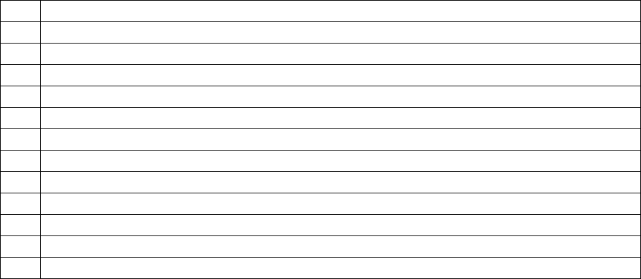
Error contents
No. Display (Cause of the error)
1 No components
2 Different component type
3 LA retry over
4 Retry over
5 Off line
6 Supply
7 Operation error
8 Laser recognition error
9 Chip rise
10 Transfer mistake
11 Feeder bank invalid
12 Stacker invalid
6 − 51
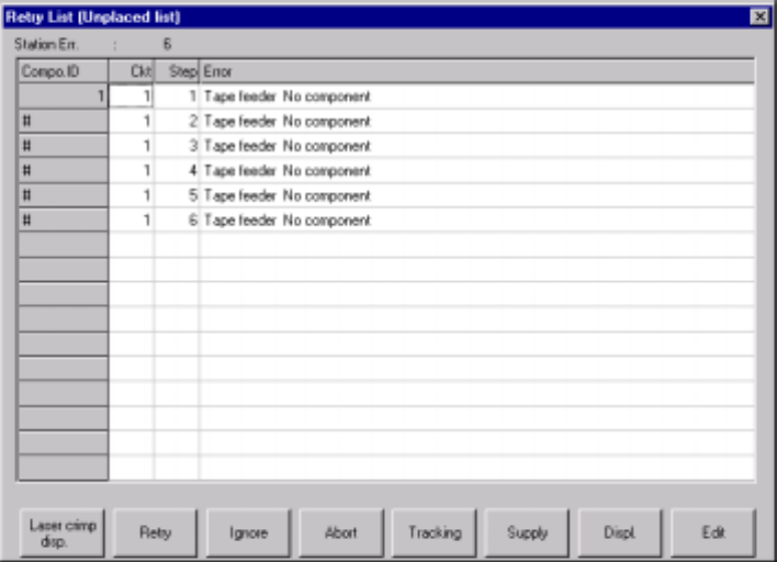
6.3.1 Retry List display after the end of board production
(1) Unplaced list
To call the retry list after board production ends, select the [Tool] command from
the menu bar, the [Error log] command on the displayed menu, then the
[Unplaced list] command.
The screen shown below (Unplaced list) in Figure 6.3.1.1 appears on the screen.
In this list, up to 100 retry errors per each station can be displayed in the order in
which the errors occurred. However, the Retry List (Supplier information) screen
in Figure 6.3.1.2 appears if there is any feeder which failed to pick up a
component although all components were placed on boards. If all components
are picked and placed, no error appears on the screen.
Figure 6.3.1.1 Retry List (Unplaced list) screen