KE2010.Instruction Manual.Ver.2.01,Rev.08.pdf - 第609页
8 − 20 (3) Con trol item Select the contr ol item with a radio but ton. (4) W indow type Select the window type w hich is to be used during measurement with the corresponding radio button. If you do not select “Meas. (ON…
8 − 19
(2) Algorithm
Select the algorithm of the laser control for execution of measurement
(SWEEP), from the combo box.
If you do not select “Meas. (SWEEP)” as the control unit, you cannot set the
algorithm here.
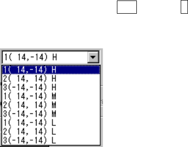
The following list appears when you press the ALT key and ↓ key at the same
time.
The number displayed left to the coordinates indicates the algorithm, and the
alphabet displayed on the right side indicates the theta rotation speed when
“SWEEP” is selected.
Algorithm 1 (14, -14) The machine finds out the position (first time) on which the
component shadow width can be the smallest with rotating
the theta axis from the current position by the pre-load
angle oppositely. Then, it rotates the theta axis 90
degrees from the position where it detected the smallest
shadow width to find out the second smallest shadow width
(second time).
This algorithm is equivalent with the algorithm 1 of the laser
recognition algorithm specified in Component data.
2 (14, 14) The machine finds out the position (first time) on which the
component shadow width can be the smallest with rotating
the theta axis from the current position by the pre-load
angle oppositely. Then, it rotates the theta axis from the
position where it detected the smallest shadow width to find
out the second smallest shadow width (second time).
This algorithm is equivalent with the algorithm 2 of the laser
recognition algorithm specified in Component data.
3 (-14, -14) The system detects the shadow of a component at the
current position without rotating the theta axis (first time).
Then, it detects another shadow with rotating the theta axis
(second time).
This algorithm is equivalent with the algorithm 3 of the laser
recognition algorithm specified in Component data.
Speed H: High M: Medium L: Low
8 − 20
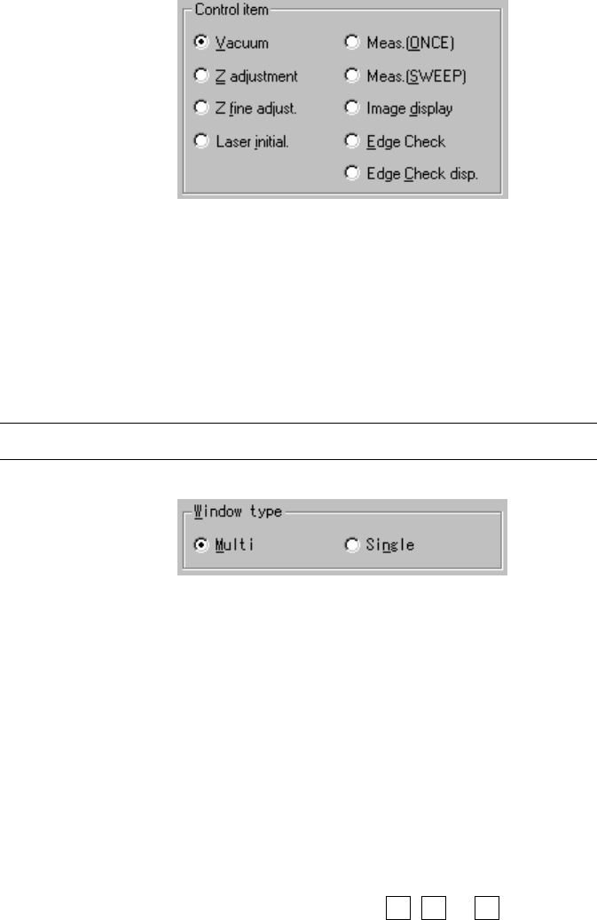
(3) Control item
Select the control item with a radio button.
(4) Window type
Select the window type which is to be used during measurement with the
corresponding radio button.
If you do not select “Meas. (ONCE)” or “Meas. (SWEEP)” as the control item,
you cannot set the window type here.
Note: You can set the window type only for the MNLA head.
(5) Control button
Each control item can be executed with the corresponding control button.
The display of the control button differs among the control items.
1) Vacuum
The control item “vacuum” turns on and / off of the vacuum of the head
selected.
When “Vacuum” of the control items is checked, select the <ON>, <OFF>,
or <ON/OFF> button or press the F3, F4 or F5 key to control the vacuum
level.
The display of the vacuum level is updated when the control has been
completed.
8 − 21
2) Z adjustment
The control item “Z adjustment” controls the Z coordinate of the head
selected.
This control is necessary to pick up components using the nozzle.
When “Z adjustment” of the control items is checked, select the <UP>,
<DOWN>, <UP/DOWN> button or press the F3, F4 or F5 key to control
the Z-axis.
The display of the coordinates is updated when the movement has been
completed.
3) Z fine adjustment
The control item “Z fine adjustment” controls finely the Z coordinate of the
head selected.
This control is necessary to move the picked component to the laser
measurement height.
When the control items “Z fine adjustment” is checked, select <UP>,
<DOWN>, <LA control> button or press the F3, F4 or F5 key to control
finely the Z axis.
The display of the coordinates is updated when the control has been
completed.
4) Laser initial
This item initializes the laser sensor of the head selected.
When the control item “Laser initialization” is checked, select the <EXEC>
button, or press the F3 key to control the laser initialization.
5) Meas. (ONCE)
This item executes the laser measurement (ONCE) of the head selected.
The laser measurement (ONCE) is the function for obtaining the
information on the shadow shot with the sensor currently. The
measurement result is displayed in the “First” field of the item
“Measurement result” on the Laser control dialog box. (See Figure 8-2-4)
When the control item “Measurement (ONCE)” is checked, select the
<EXEC>, <LA control> button or press the F3 key or F5 key to control the
measurement.
The display of the measurement result is updated when the control has
been completed.