KE2010.Instruction Manual.Ver.2.01,Rev.08.pdf - 第520页
6 − 144 ① Status OK: Centering is done successf ully. Number: Cent ering (Each number indicates t he error code num ber of the laser status). ② Outli ne The component minimum width (dimensions) detected when it is center…
6 − 143
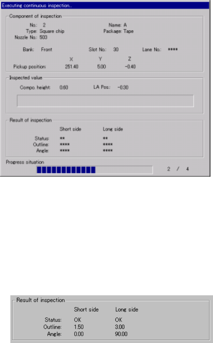
(2) Screen displayed during continuous check
While the system is checking laser height continuously, the following dialog
box appears on the screen. The description of a component being checked,
component pick-up position and the result of inspection are displayed on this
dialog box. In addition, the progress condition of the continuous check
appears also.
Figure 6.7.2.5.2.3 Laser height continuous check dialog box
1) Result of inspection
After checking laser height, the results are displayed in this "Result of
inspection" column.
The "Short side" and the "Long side" indicate the data when the system
detects the minimum width of a component for the first time and second
time respectively.
The results are valid only if the status of both "Short side" and "Long side"
is "OK".
6 − 144
① Status
OK: Centering is done successfully.
Number: Centering
(Each number indicates the error code number of the laser
status).
② Outline
The component minimum width (dimensions) detected when it is
centered successfully is displayed here.
③ Angle
The angle when a component is centered is displayed here.
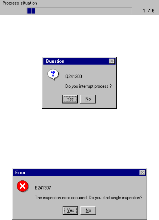
2) Progress situation
This slider bar indicates the progress situation of the current continuous
check operation.
To forcibly abort the check, press the <STOP> button. The following
dialog box appears on the screen. Select whether to abort the check or
not.
Figure 6.7.2.5.2.4 "Question - to interrupt process" dialog box
3) Check error
If a check error occurs, that is, the laser status is not "OK", the following
dialog box appears on the screen to allow you to enter Single check
mode.
Figure 6.7.2.5.2.5 Continuous check error dialog box
6 − 145
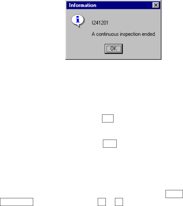
4) End of continuous check
When the system finishes checking all components which satisfy the
conditions you specified, the following dialog box appears on the screen.
Figure 6.7.2.5.2.6 "Information - end of Continuous laser position
inspection" dialog box
6.7.2.5.3 Single inspection
• When you click the <INSP.> button (F10 key), the system starts checking a
component. When it finishes checking the component, the result appears on
the screen.
• When you click the <MEAS.> button (F10 key), the system starts measuring a
component. When it finishes measuring a component, the result appears on
the screen.
• On the "Inspection" screen, you can manually enter the pick-up position or use
the teaching function to enter it. When you check the check box "The taught
result is reflected in the pick data.", the taught data is stored into Pick data.
• On the "Laser position measurement" screen, pressing the NEXT or
PREVIOUS key of the HOD or the F5 or F6 key moves the component pick-up
position to the alternative component.
• In Continuous check mode, pressing the <START> switch resumes the
continuous check.