KE2010.Instruction Manual.Ver.2.01,Rev.08.pdf - 第537页
6 − 161 6.7.3.6. 5 Continuous inspecti on error dialog box If the inspection result indicates “NG” , the f ollowing dialog box appears and it allows you to enter the system to Sing le Inspection mode. Figure 6.7. 3.6.5 C…
6 − 160
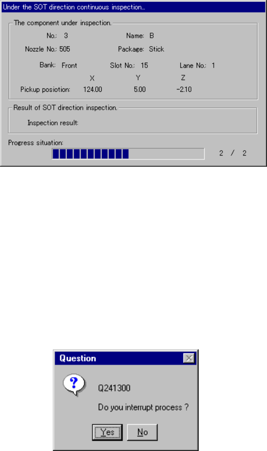
6.7.3.6.3 “Under the SOT direction continuous inspection…” dialog box
During continuous inspection, the system displays the following dialog box on
which data on a component being checked, the inspection progress, and the
inspection result are displayed.
Figure 6.7.3.6.3 “Under the SOT direction continuous inspection…” dialog box
− Result of SOT direction inspection
After inspection, the result is displayed here, OK or NG.
6.7.3.6.4 Interruption dialog box
To interrupt the inspection being executed forcibly, press the <STOP> button.
The following dialog box appears on the screen. Select whether to stop the
inspection or not.
Figure 6.7.3.6.4 “Question” dialog box for interrupting the current inspection
6 − 161
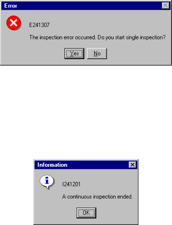
6.7.3.6.5 Continuous inspection error dialog box
If the inspection result indicates “NG”, the following dialog box appears and it
allows you to enter the system to Single Inspection mode.
Figure 6.7.3.6.5 Continuous inspection error dialog box
6.7.3.7 End of continuous inspection
When the system finishes checking all components you specified, the following
dialog box appears that notifies you of end of continuous inspection.
Figure 6.7.3.7 End of inspection dialog box

7 − 1
CHAPTER 7 MACHINE SETUP
7.1 Overview
Table 7.1.1 shows the items to be set on the Machine Setup menu.
Table 7.1.1 Machine setup items
No. Machine setup group Description
1 ATC nozzle setup
*1 The ATC numbers
may vary
depending on the
model you use.
*1 Assigns nozzles to ATCs whose numbers are 1 to 24 (KE-2010).
*1 Assigns nozzles to ATCs whose numbers are 1 to 30 , and A ,B
( KE-2020).
*1 Assigns nozzles to ATCs whose numbers are L1 to L21, and R1 to R21.
(KE-2030)
*1 Assigns nozzles to ATCs whose numbers are 1 to 18, and A to C
(KE-2040).
Sets also the number and type of the nozzles to be assigned, the vacuum
value and the laser height for each nozzle when it is attached on the head.
2 Vacuum value without
nozzle
Vacuum value obtained when the nozzle is not mounted.
3 Reference pin position Positions of the reference and follower pins from the origin.
4 Shape clamp position Position of the edge reference from the origin.
5 MTC shuttle pick position
(Not available for a
KE-2030)
MTC shuttle pick position
6 MTS position offset
(Not available for a
KE-2030)
MTS first mark position
MTS second mark position
7 Component scrap
position
The position where IC components are discarded.
The position where chip components are discarded.
8 IC conveyor belt position
(Not available for a
KE-2030)
The position where the IC collection belt is installed.
The position on the IC collection belt where the components are discarded.
9 Head wait position Position on which the head pauses to protect a component
10 Device enable With this setup item, set to “Not used” a device unit (such as a head and
MTC) which cannot be used for producing PWBs due to malfunction.
If such a device unit is set as “Not used”, a production operation completes
normally even though the unit is indispensable to production of PWBs.
11 Multi-station line Defines whether the machine is connected to an HLC to incorporate it into
a multi-station line
If it is incorporated in the line, set the IP address.
12 PWB conveyor Sets delay for PWB conveyor sensor (the delay of the PWB conveyor
sensor for a cut out board or punch hole board), (units of delay (time [ms]
or length [mm]), whether to perform the automatic PWB width adjustment
function, back-up table board lower limit, acceleration, and stroke.
13 Vacuum table Sets the time of period while the vacuum table is to be operating.
14 Signal light Sets the signal light pattern for each operation phase.
15 Bad mark sensor
teaching
Bad mark position
Non-bad mark position
16 Coplanarity Number of retry (KE2020, 2040)
Measure plane