KE2010.Instruction Manual.Ver.2.01,Rev.08.pdf - 第196页
4 – 89 ② V acuum Lvl (level) W hen producing PW Bs, the machine uses the vacuum level obtained when no component is pick ed (to be set on t he Machine Setup menu) and the value set with this V acuum level menu item to de…
4 – 88
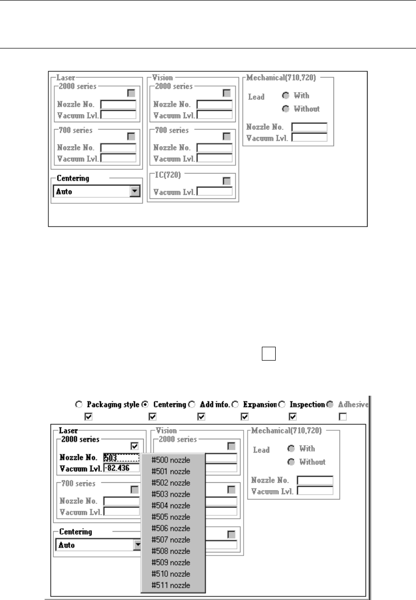
4.7.4 Tack control section (Centering page)
Select “Laser” because this item is specific only to “Laser”.
No other centering method cannot be selected.
Note: When you read data from another machine or database into this machine, the
menu items “Vision” and “Mechanical” are disabled, then Component data
becomes incomplete.
Two menu items “Vision” and “Mechanical” are disabled, so you cannot set any data
for these items.
① Nozzle No.
Directly enter the nozzle number into the edit box or select one from the pop-up
menu which is shown below.
When you press the right button of a track ball or F2 key of a keyboard, the
following pop-up menu appears on the screen. Select the desired nozzle number.
4 – 89
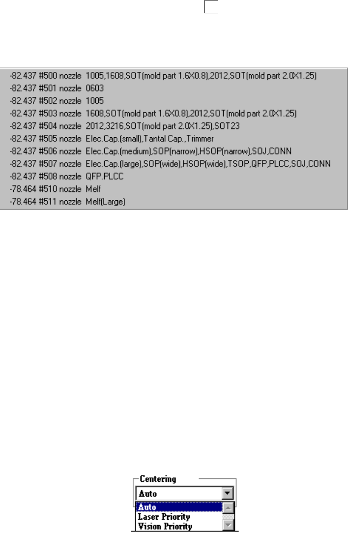
② Vacuum Lvl (level)
When producing PWBs, the machine uses the vacuum level obtained when no
component is picked (to be set on the Machine Setup menu) and the value set
with this Vacuum level menu item to decide whether a component can be picked
up with the vacuum level you set here.
Enter the vacuum value to be used for picking up a component with the nozzle
which is designated with the menu item “Nozzle No.”. Directly enter a value or
press the right button of a track ball or the F2 key of a keyboard to open the
pop-up menu, then select the desired value.
Component pick-up vacuum value
− When you enter the vacuum value, the displayed value changes a little.
This is caused by AD conversion to improve the resolution, so this is not an
error.
Example: You enter - 82.437 kPa → The screen indicates -82.436 kPa
− The displayed component pick-up vacuum level is just a reference value.
Since the finishing applied to the surface of a component varies depending
on its manufacturer, measure a component with this machine before actually
using the vacuum level you set here.
③ Centering
Use the "Centering" combo box to select the centering condition.
If both centering methods are selected, this box allows you to specify which
centering method is used with the higher priority, laser or vision.
)
(Not available for a KE-2040)
4 – 90
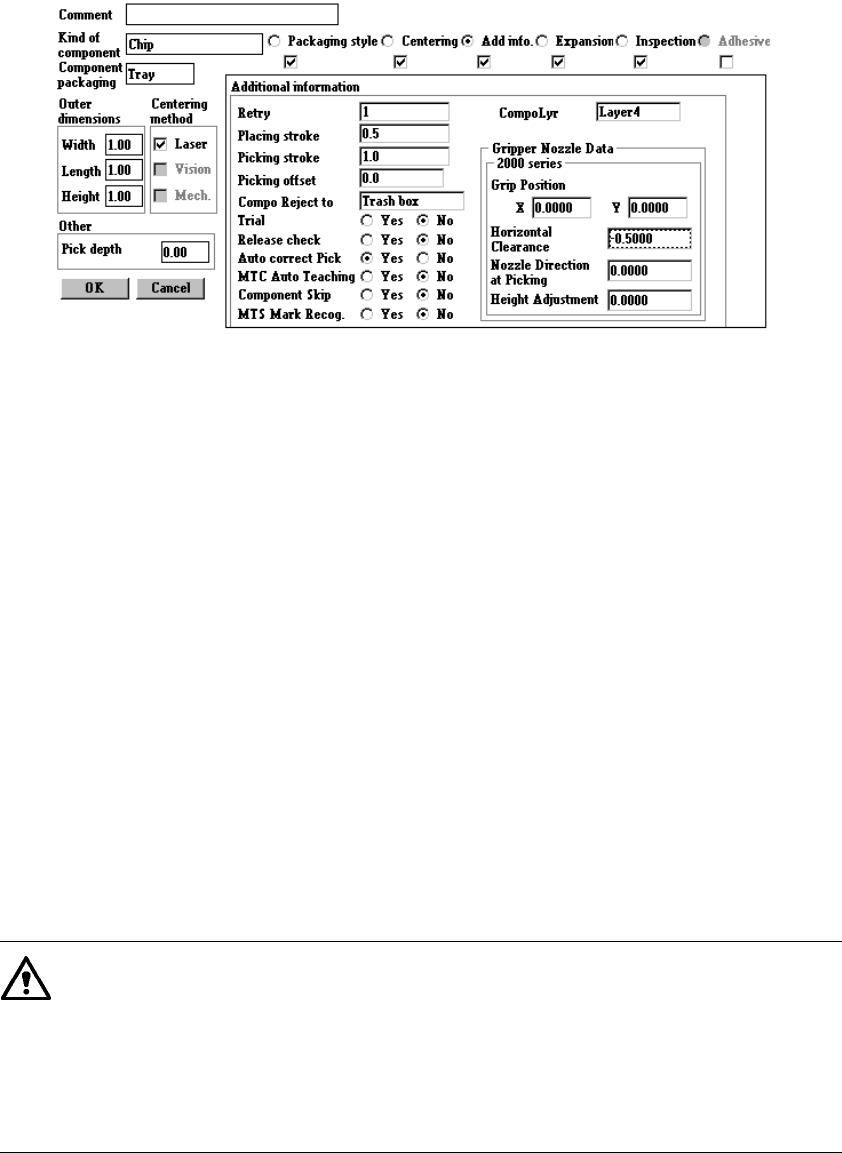
4.7.5 Tack control section (“Add. info.” page)
Since the default values are set at the items provided on the Additional information
page, normally you do not have to change them. Only if you want to change the
default setting, open the Additional Information window. Note that some items may
be reset to their default values if you change settings on the kind of component,
Centering or Component packaging page after you change the setting of items on the
Additional Information page.
●
Additional information
①
Retry
Enter in the edit field the number of retries to be performed when a component
pick-up error occurs. The yellow signal light flashes to warn you when an
overretry occurs in production.
②
Placing stroke
Enter in the edit field the placing stroke for pushing a component from the top of a
board.
③
Picking stroke
Enter in the edit field the picking stroke for pushing the tip of a nozzle to pick up a
component.
④
Picking offset
Enter in the edit field the picking offset for pushing the tip of a nozzle from the
component picking-up height to pick up embossed tape. The system uses this
value to automatically calculate a value of “Z” on the Pick data screen when
“Tape” is selected as the packaging style and embossed tape is selected as the
“Tape Width”.
If you change the “Picking offset” value of this menu even when the
coordinates of the component picking up position are already entered, the
system will not calculate the component pick-up position again. If you change
the setting of “Sply” to “AUTO” on the Pick data corresponding to the
Component data you changed, and specify the pick-up position again, the
system calculates the coordinates of the pick-up position again, and they are
entered to “Z”.