KE2010.Instruction Manual.Ver.2.01,Rev.08.pdf - 第452页
6 − 76 6.4.8 Checking to see if a laser head is stained W hen y ou check t he check box “Check dir ty of Laser sensor.” of the “ Production (Function 2)” t ab that is invoked f rom the Operat ion Option screen, the syste…
6 − 75
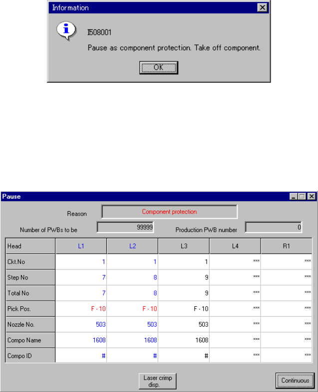
6.4.7 Pause as component protection
If a recognition error occurs at a component designated as a protective component
specified in the component data of production program (on the Expanded window),
the machine is put in the pause state and the message box appears as shown in
Figure 6.4.7.1.
Figure 6.4.7.1 "Pause as component protection" dialog box
Remove the component being picked by the nozzle with your hand, and select the
<OK> button. Then, the machine is put in the pause state with the dialog box
displayed as shown in Figure 6.4.7.2.
Figure 6.4.7.2 Pause dialog box due to component protection
Pressing the <START> switch on the panel of the main unit scraps the component,
and then restarts the production. Pressing the <STOP> switch puts the machine in the
pause state with the production stop dialog box displayed.
6 − 76
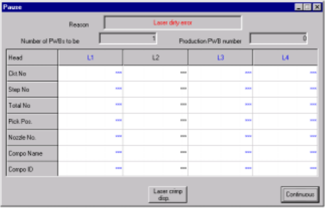
6.4.8 Checking to see if a laser head is stained
When you check the check box “Check dirty of Laser sensor.” of the “Production
(Function 2)” tab that is invoked from the Operation Option screen, the system checks
to see if laser heads are stained when a board is sent into the machine. If the
system detects any stain stuck to the laser head(s), the system pauses.
− The laser head(s) that is (are) found to be stained is displayed in blue on the
screen.
− The stained head stops temporarily after moving to the front side. Clean the
laser head.
Figure 6.4.8.1 Pause dialog box
− The <Laser Waveform Display> button appears on the “Pause” or “Retry List”
screen. Note that the head moves up and down to check to see if a laser head is
stained when you click the <Laser Waveform Display> button.
6 − 77
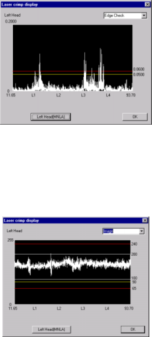
* When you click this <Laser comp disp.> button, the system displays the result of
the edge check on the screen.
Figure 6.4.8.2 “Edge Check display” dialog box
(Screen example when you use a KE-2020)
− When you click the <Left Head (MNLA)> button, the machine displays the
edge check result of the left head.
− When you click the <Right Head (FMLA)> button, the machine displays the
edge check result of the right head.
* When you select <Image> from the combo box, the system displays the waveform
of the image.
Figure 6.4.8.3 “Image” display dialog box (Screen example: KE-2020)
− When you click the <Left Head> button, the system displays the image
waveform of the left head.
− When you click the <Right Head> button, the system displays the image
waveform of the right head.