KE2010.Instruction Manual.Ver.2.01,Rev.08.pdf - 第62页
1 − 45 1.5 Installation Check CA UTION Check that the machine is level ly ing completely flat on the floor. Check that the lock nuts are tightened securely on t he four feet of the machine. Check that correct electrical …

1 − 44
Table 1.4.7 Matrix tray changer interface connector pin assignments
Signal name
Signal name
Connector used
1 RD0 26 GND
2 RD1 27 WRITE0 (N)
3 RD2 28 GND
4 RD3 29 R/B0(N)
5 GND 30 GND
6 GND 31 R/B1(N)
7 RD4 32 POWON (N)
8 RD5 33 EMG (N)
9 RD6 34 MTC EMG
10 RD7 35 C • OPEN (N)
11 GND 36 MTC OPEN
12 GND 37 + 5V
13 WD0 38 + 5V
14 WD1 39 + 5V
15 WD2 40 + 5V
16 WD3 41
17 GND 42
18 GND 43
19 WD4 44
20 WD5 45
21 WD6 46
22 WD7 47
23 GND 48
24 GND 49
25 WRITE1 50
Yamaichi Electronics
IDC type
socketNCS050-000-
BS
Table 1.4.8 Matrix tray changer power connector pin assignments
Signal name
Connector used
1 U
2
3
4 FG
5 V
6 W
7
Square-type flange receptacle
AMP 21198-1
Socket contact
AMP 66360-2
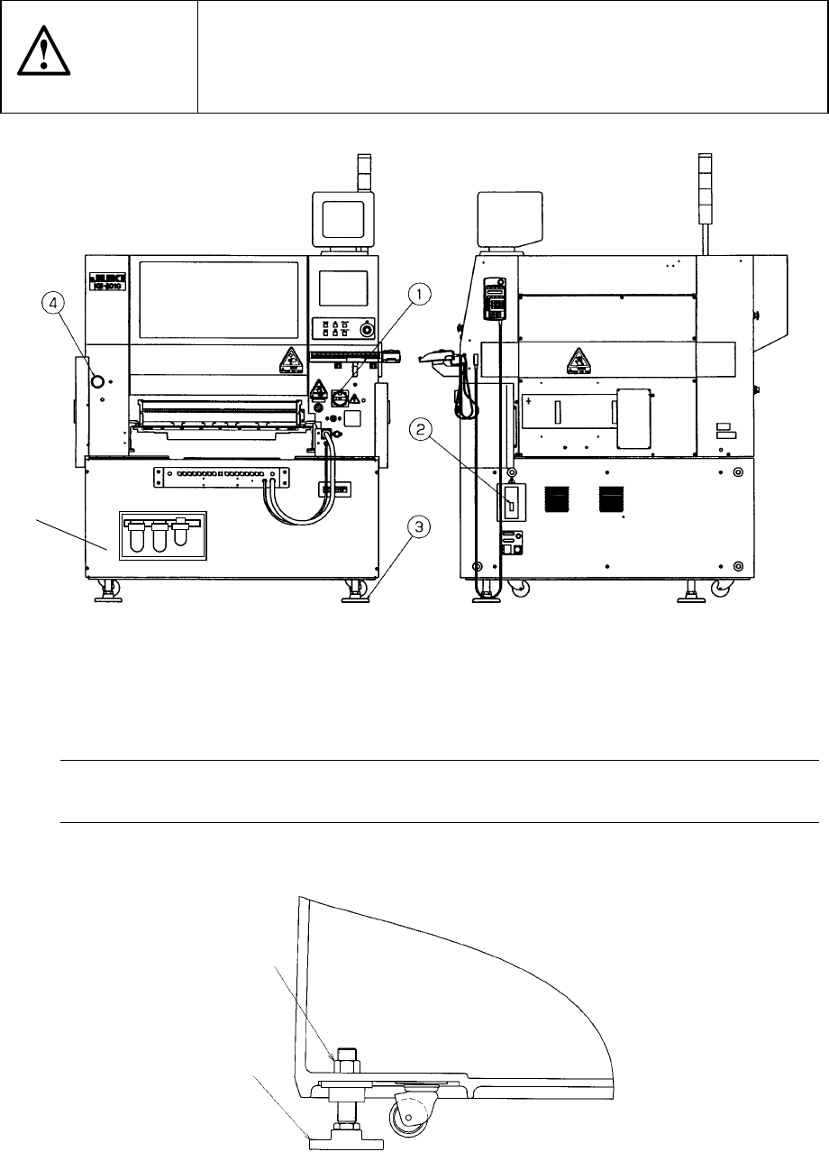
1 − 45
1.5 Installation Check
CAUTION
Check that the machine is level lying completely flat on the floor.
Check that the lock nuts are tightened securely on the four feet of the
machine.
Check that correct electrical power and air are supplied to the machine.
① Main switch ② Breaker ③ Adjuster
④ Pressure gauge ⑤ Filter regulator
Note: To avoid the laser sensor detection error, install the machine where not subject
to direct sunlight.
Figure 1.5.1
Figure 1.5.2
Lock nut
(Four)
③
⑤
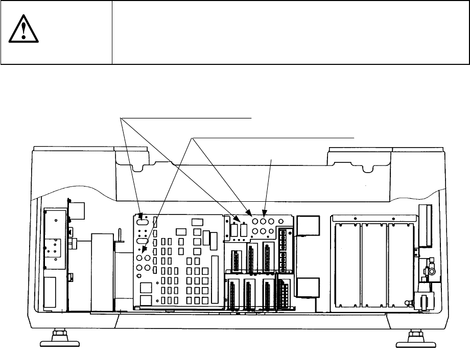
1 − 46
1.6 Checking circuit protector
If the machine does not operate properly after it has been turned ON, check the
condition of the circuit protector in the power unit found on the back side of the
machine. If push-button type the circuit protector front face protrudes to show the
red mark, push the face back in. When the lever of the lever-type circuit protector is
lowered, raise it.
CAUTION
To avoid risk of serious injury or death caused by electric shock hazard,
turn off the main power switch of the house current which is installed in
the building where the machine is used.
Note that it is not the main power switch of the machine.
Figure 1.6.1
Lever-type circuit protectors
Push-button type circuit protectors
Power unit