KE2010.Instruction Manual.Ver.2.01,Rev.08.pdf - 第582页
7 − 45 (3) Def ault values Signal li ght pattern No. Phase Red Y el low Green Buzzer Remark s 1 Initial s tate (P ower on) All colors of lam ps light . ■ ■ ■ OFF 2 Menu The yellow lamp li ghts. ― ■ ― OFF 3 Data input The…
7 − 44
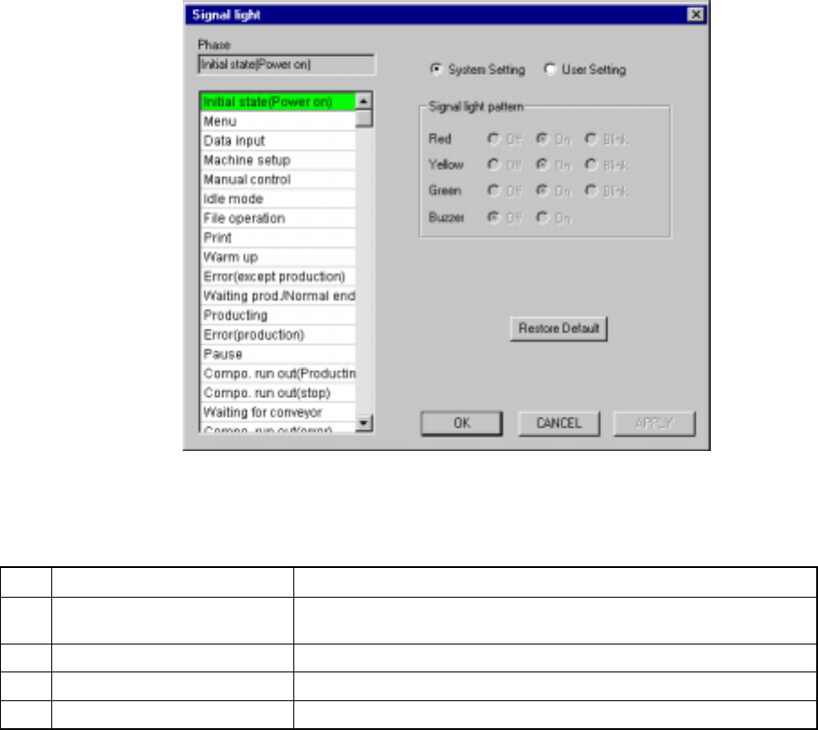
7.2.2.14 Signal light
A screen as shown in Figure 7.2.2.14.1 “Signal light setting dialog box” appears
when [Signal light] is selected on the [Setting Group] menu.
Figure 7.2.2.14.1 Signal light setting dialog box
(1) Setting items
No. Item Description
1 Signal light pattern
(Red, Yellow, Green)
Sets the light pattern of the signal light in each operation phase.
2 Signal light pattern (Buzzer) Sets ON/OFF of the buzzer in each operation phase.
3 System setting/User setting Sets the data used for a user signal pattern.
4 System Default Copies the system setting data to the user setting data.
(2) How to set
① Signal light (Red, Yellow, Green)
− Using the radio button, set on, off, or blink.
② Buzzer
− Using the radio button, set off or on.
③ System Setting/User Setting
− Select the data to be used with either of these radio buttons.
− Selection of the “System Setting” radio button allows you to see the
settings of the system initial values only. You cannot change them.

7 − 45
(3) Default values
Signal light pattern
No. Phase
Red Yellow Green Buzzer
Remarks
1 Initial state (Power on) All colors of lamps light.
■
■
■
OFF
2 Menu The yellow lamp lights.
―
■
―
OFF
3 Data input The yellow lamp lights.
―
■
―
OFF
4 Machine setup The yellow lamp lights.
―
■
―
OFF
5 Manual control The yellow lamp lights.
―
■
―
OFF
6 Idle mode The yellow lamp lights.
―
■
―
OFF
7 File operation The yellow lamp lights.
―
■
―
OFF
8 Print The yellow lamp lights.
―
■
―
OFF
9 Warm up The yellow lamp lights.
―
■
―
OFF
10 Error (except production) The red lamp lights.
■
―
―
OFF
11 Waiting prod/Normal end All colors of lamps light.
■
■
■
OFF
12 Producing The green lamp lights.
―
―
■
OFF
13 Error (production) The red lamp lights.
■
―
―
OFF
14 Pause The yellow lamp lights.
―
■
―
OFF
15 Compo. run out (producing) The green lamp lights and
yellow lamp flashes.
―
□
■
OFF
16 Compo. run out (stop) The red lamp lights and
yellow lamp flashes.
■
□
―
OFF
17 Waiting for conveyor The green lamp flashes.
―
―
□
OFF
18
Production
Compo. run out (error) The red lamp lights and
yellow lamp flashes.
■
□
―
OFF
19 Emergency stop The red lamp lights.
■
―
―
OFF
20 Returning to the origin (home position) The yellow lamp lights.
―
■
―
OFF
21 Self diagnostics The yellow lamp lights.
―
■
―
OFF
22 Trouble analysis The yellow lamp lights.
―
■
―
OFF
23 Self calibration The yellow lamp lights.
―
■
―
OFF
24 Settings changing The yellow lamp lights.
―
■
―
OFF
25 Producing at one station and waiting a
board to be transported at another station
The green lamp flashes.
―
―
□
OFF For a KE-2030
26 Others All colors of lamps light.
■
■
■
OFF
■
: ON
□
: Flashes
―
: OFF
* The initial status of the machine means the duration before it is set ready to be
operated after power is turned on. The desktop is the initial display of the
screen after the machine quits the initial status.
(4) Signal Light Buzzer
A signal light buzzer is optional, so be sure to set the Buzzer radio button of the
signal light pattern to OFF when you use a signal light not equipped with a
buzzer.
The buzzer sounds when the machine enters each status described in Table
above only if the Buzzer radio button of the signal light pattern is set to ON. To
stop the buzzer, press any key on the front panel such as the <START> key
and <STOP> key. In this case, the key you pressed just stops the buzzer, and
does not perform its own function.
7 − 46
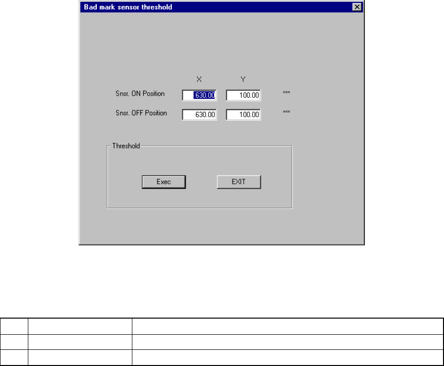
7.2.2.15 Bad mark sensor teaching
When you select the setting item "Bad mark sensor teaching", the "Bad mark
sensor teaching" dialog box appears on the screen as shown in Figure 7.2.2.15.1.
Figure 7.2.2.15.1 "Bad mark sensor teaching" dialog box
(1) Setting items
No. Item Description
1 Snsr. ON Position Sets the sensor turning ON position.
2 Snsr. OFF Position Sets the sensor turning OFF position.
(2) How to set
− Enter the X- and Y-coordinates separately directly from a keyboard.
− Use the HOD to teach the coordinates with a camera.
In this case, both X and Y values are loaded at the same time regardless of
the input focus position.
(3) Actions taken after you click the <DONE> button
− When you click the <DONE> button, the "Threshold - Initialize" dialog box
appears on the screen, then the system initializes the bad mark sensor.
Next, the "Threshold - Execution" dialog box appears on the screen which
indicates the system automatically performs the teaching operation.