KE2010.Instruction Manual.Ver.2.01,Rev.08.pdf - 第227页
4 – 120 ③ Pos (Position) Enter the m ounting hole num ber which is indicated with the mounting mark on the tray holder . Figure 4. 8.2.3.1. 1 shows how to m ount a holder and tr ay assignment. Figure 4.8.2. 3.1.1 How to …
4 – 119
4.8.2.3 Tray
4.8.2.3.1 Tray holder
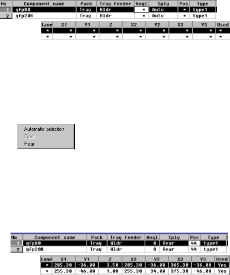
When you select a tray holder, the following screen is displayed.
− The parameters "Pack", "Tray Feeder" and "Type" set as Component data
appear here: you cannot change any of them. To change either one,
change the setting of Component data.
① Sply (Supply)
This parameter specifies whether a tray is automatically selected or set on the
rear.
The Optimization utility assigns trays to the machine
Trays are assigned to the rear side.
• When you select "Automatic selection", the Optimization utility automatically
assigns trays to the machine, so you do not have to enter any data to other
items.
• When the Optimization utility is executed, items at which an asterisk mark
"*" is displayed (excluding the parameter "Lane") are automatically set.
• When you select "Rear", you can enter data to items at which an asterisk
mark is displayed (excluding the parameter "Lane").
② Angl (Angle)
See the description of the parameter "Angl" for a tape/bulk feeder.
4 – 120
③ Pos (Position)
Enter the mounting hole number which is indicated with the mounting mark on
the tray holder.
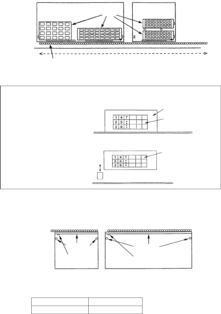
Figure 4.8.2.3.1.1 shows how to mount a holder and tray assignment.
Figure 4.8.2.3.1.1 How to mount a holder and tray assignment
Note: Pick-up sequence of components fed by a tray holder
− MTS / tray holder
− MTC
− Tray holder
There are two types of tray holders provided: Type 1 (full specifications) and
Type 2 (half specifications). Each type of tray holder is shown in the figure
below.
* To mount a tray holder on the machine, align the mounting marker with the
feeder mounting hole to insert the holder to the machine.
Occupied feeder mounting holes
Type 1 40
Type 2 21
Rear
Tray holder type 1
Trays
Tray holder type 2
Tray holder mountable area
Feeder mounting hole
PWB transport path
MTS / tray holder
Tray
Tra
y
Shuttle
Stoppers
Mounting marker
Type 2
Stoppers
Mounting marker
Type 1
4 – 121
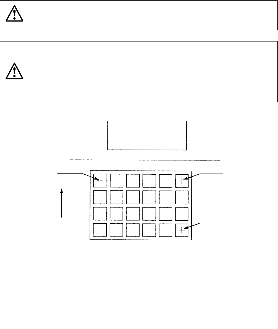
④ X1, Y1, Z, X2, Y2, X3, Y3
These coordinates specify the component pick-up position on three corners of
a tray.
When you enter the "Sply" parameter, the component pick-up position is
automatically calculated, then displayed based on Component data.
Once a value is entered to each coordinate parameter, you can change each
coordinate separately (by teaching also).
CAUTION
To avoid a risk of injury, do not place your hand in the machine, nor
move your face or head close to the machine while the machine is
performing teaching operation.
CAUTION
If the bank is never recognized (since the machine zeroes, or the bank
moves down then up), it may be recognized automatically before the
machine moves to the pick position. Since the head moves across the
feeder while the feeder bank is being recognized, do not place your
hand in the machine, nor move your face or head to the machine.
Especially, take care when the feeder bank is recognized not from the
menu but during teaching or tracking a pick position.
Figure 4.8.2.3.1.2 Pick-up coordinates on a tray holder
If you are to teach the coordinates
When the cursor is located at the cell X1 or Y1, you can enter the coordinates X1 and
Y1.When the cursor is located at the cell X2 or Y2, you can enter the coordinates X2 and
Y2.When the cursor is located at the cell X3 or Y3, you can enter the coordinates X3 and
Y3.When the cursor is located at the cell Z, you can enter the coordinate "Z".
⑤ Used
See the description of the parameter "Used" for a tape feeder.
PWB
(
X1
,
Y1
)
(
X2
,
Y2
)
Feeding
direction
(
X3
,
Y3
)
Side