KE2010.Instruction Manual.Ver.2.01,Rev.08.pdf - 第202页
4 – 95 ⑨ Laser algorithm Select the alg orithm f or laser recognit ion with the combo box Laser algor ithm 0: Rotates a component f rom the pick -up position by the placement ang le, then places it. (f or a component whi…
4 – 94
③
Pick Z up
Using this combo box, set the acceleration (for preventing the components
from dropping) of Z-axis up movement at the pick position.
You can select any of the same choices as those displayed in the "XY"
combo box.
Specify "Med." or "Slow" if the surface area of a component is large, so its air
resistance is high, or if a component is heavy.
④
Place Z down
Using this combo box, set the acceleration (for adjusting the stress placed on
a component) of Z-axis down movement at the placement position.
You can select any of the same choices as those displayed in the "XY"
combo box.
Specify "Med." or "Slow" if a very small component is fed with a tape feeder
and it can be placed unstably.
This selection is useful to adjust the vertical stress imposed on a component
also.
⑤
Place Z up
Using this combo box, set the acceleration (for placing components stably) of
Z-axis up movement at the placement position.
You can select any of the same choices as those displayed in the "XY"
combo box.
⑥
Theta
Using the combo box, set the θ rotation speed.
− test 1 (When measuring)
Set the acceleration of the theta axis to be applied when a component is
recognized with laser.
− test 2 (When not measure)
Set the acceleration of the theta axis to be applied not when a component
is recognized with laser.
You can select any of the same choices as those displayed in the "XY"
combo box.
⑦
Place Offset
Enter the placement offset for unsymmetric components.
⑧
Laser
Enter the offset from the surface of the component to the laser.
This item is enabled only when an LA/LAHD head or MNLA/FMLA head is
used.
4 – 95
⑨
Laser algorithm
Select the algorithm for laser recognition with the combo box
Laser algorithm 0: Rotates a component from the pick-up position by the
placement angle, then places it.
(for a component which cannot be recognized with laser, but
you want to place on a board.)
Laser algorithm 1: Finds a side whose shade width is the narrowest (first
smallest shade A), then rotates a component from this side to
the + 90 degrees position. Next, detect the narrowest side
(second smallest shade B) to correct a positioning error
and/or angle error, then places the component.
(for a chip component)
Laser algorithm 2: Finds a side whose shade width is the narrowest (first
smallest shade A), then rotates a component from this side in
the positive direction while aligning it with laser. Next, detect
the narrowest side (second smallest shade B) to correct a
positioning error and/or angle error, then places the
component.
(for a component which has a lead(s) such as an SOP)
Laser algorithm 3: Detects the shade of a component which is ready for
pick-up (first smallest shade A), then rotates the component
from the detected side to the + 90 degrees position. Next,
detect the narrowest width (second smallest shade B) to
correct a positioning error, then places the component.
(for a cylindrical-shaped component)
⑩
Pre-rotate
Set how much a laser recognition component which is picked up shall be rotated
(pre-rotate angle) before it is centered. Enter the pre-rotate angle in the edit
field When you enter the dimensions for the first time, the default value is set
here. When you change them, the default value is not set.
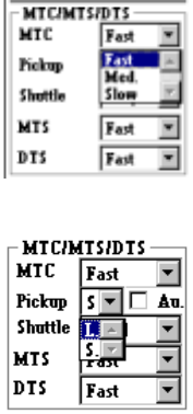
(2) MTC/MTS
①
MTC
Specify the speed of the MTC in the combo box.
• This setting prevents a light-weight
component from popping on a tray.
②
Pickup
Specify the MTC pick-up pad type in the combo box.
• This setting allows you to select the pick-up
pad of the pick-up unit depending on a
component to be picked. (See Table 4.7.6
“Default values for a pick-up pad”.)
• When you select the “Au.” (Automatic) the
system selects both pads for the same
component type and picks a component
during production.
Note that the system may not pick up a
component depending on its size.
4 – 96
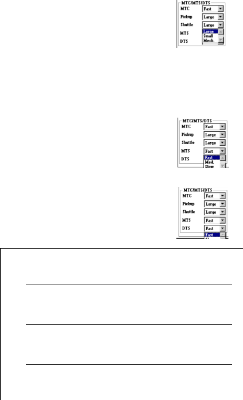
③
Shuttle
Specify the MTC shuttle pad type in the combo box.
• This setting allows you to select the pick-up
pad of the shuttle depending on a
component to be picked. (See Table 4.7.6
“Default values for a pick-up pad”.)
• When you select "Mech.", the machine
cannot return a component onto the MTC.
Select a choice other than "Tray restore" at
the control item "Compo Reject to"
displayed on the "Add Info." page of the
Tack Control section.
④
MTS
Specify the MTS speed in the combo box.
• Specify the speed for pulling out a tray here.
⑤
DTS
Specify the DTS speed in the combo box.
• Specify the speed for pulling out a tray here.
− The default values for a pick-up pad are shown in the table below.
Table 4.7.6 Default values for a pick-up pad
Display on the
screen
Default values
Pickup – When the shorter side of component dimensions
is less than 16 mm: Small
16 mm or more: Large
Shuttle – When the component type is BGA: Mech.
– When the component type is other than BGA,
and the shorter side of the component
dimensions is less than 16 mm: Small
16 mm or more: Large
Note: You may have to change the shuttle setting depending on the
lead length or component shape.