KE2010.Instruction Manual.Ver.2.01,Rev.08.pdf - 第53页
1 − 36 1.2.7 OCC parts identification (1) Off set correction camera The machine is equipped with a coaxial light and polar izing f ilter as t he standard devices. The camera det ects a BOC mar k and cor rects the det ect…
1 − 35
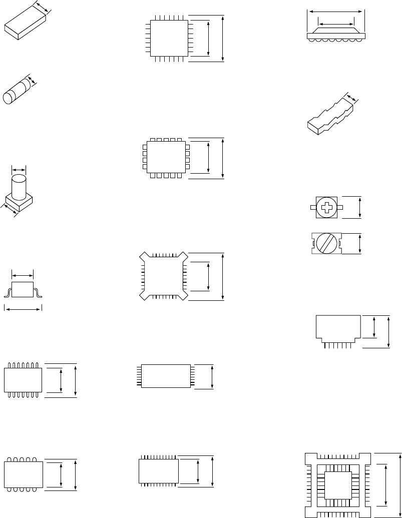
(3) Minimum component width (D) of each component.
!1
A
D
A
D
W
D
A
D = A
A
D
A
D
A
D
A
D
D
A
D = A
A
A
A
D = A
AA
D = A
A
D
A
D
A
D
①
Square chip
②
MELF
③
Aluminum
electrolytic capacitor
D = A + 0.5mm
④
SOT
⑤
SOP
⑥
SOJ
⑦
QFP
⑫
BGA
⑧
PLCC
⑨
BQFP
⑩
TSOP
⑪
TSOP2
⑬
Network resistor
⑭
Trimmer
⑮
One-way lead connector
⑯
Gull wing socket
J lead socket
Socket with bumper
1 − 36
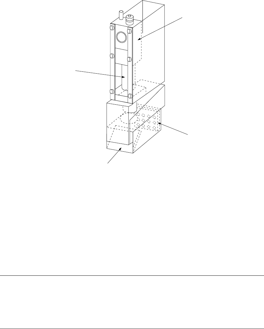
1.2.7 OCC parts identification
(1) Offset correction camera
The machine is equipped with a coaxial light and polarizing filter as the standard
devices. The camera detects a BOC mark and corrects the detected mark
automatically.
①
OCC camera
②
OCC lens
③
Illumination LED board
④
Mirror box
Figure 1.2.7.1
Adjusting the polarizing filter
1) Place a white ceramic board on the calibration block, then move the camera over
this board.
2) Loosen the screw to turn the filter holder to the right and left. When the screen
becomes brightest, fix the screw.
①
④
③
1 − 37
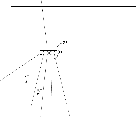
1.3 X, Y, and Z Axes Descriptions
The following four axes (X, Y, Z, and θ) are numerically controlled in this machine.
(1) X- and Y-axis
The X-axis represents the left and right directions of the machine, while the
Y-axis represents the front and rear directions: a position is given as X = 000.00
mm and Y = 000.00 mm in increments of 0.01 mm. Two coordinate systems are
available: one given by the production program and another given by teaching
operation. Both coordinate systems are automatically changed, so you do not
have to switch the coordinate system by yourself.
(2) Z-axis
The Z-axis represents the height, given as Z =
○○
.
○○
mm, in 0.01-mm
increments. The upward direction is positive (+), with the top side of a board
clamped (any jig is not used) being 0.
(3) θ-axis
The q-axis represents the rotation angle of the head, given as "A =
○○
.
○○
" (in
0.05 increments.) The value is positive for counterclockwise rotation and
negative for clockwise rotation.
Figure 1.3.1
Head unit
X axis
Y axis
OCC
First nozzle axis
Second nozzle axis
Fourth nozzle axis
Third nozzle axis