KE2010.Instruction Manual.Ver.2.01,Rev.08.pdf - 第464页
6 − 88 Message Meaning W ARNING PW B/BOC m ark (*6) is outsi de PW B or circuit. There is a circuit located outside the PW B. ↓ Place/No.*1 There is supply device where the head can't mov e. There is a supply dev ic…

6 − 87
Message Meaning
Error
Place/No.*1 IC mark %d recognition
teaching non-completion.
IC mark recognition teaching is not completed.
↓
Place/No.*1 Template can’t be used.
(Machine setup isn’t check.)
The user-defined template is used as an IC mark.
(Template matching is set to “unused” at machine setup.)
↓
Place/No.*1 It is not possible to move
in the head.
There is a placement point to which the head cannot
move.
↓
Place/No.*1 Mark can't be recognized.
(Ckt. rotate isn't 90°.)
Unless the circuit arrangement is in units of 90°, an
unrecognizable type of IC mark is used.
↓ Place/No.*1 IC mark is same position. The IC mark coordinates are overlapped.
↓
Place/No.*1 The head is not specified
by optimization.
After optimization, there are placement points to which
any head is not assigned.
↓ Comp./No*2 Incompleteness. Component data is incomplete.
↓
Comp./No.*2 There is not enough
nozzle (*5) to product.
The nozzle specified in component data is not set in ATC.
↓ Pick/No.*3 Incompleteness. Pickup data is incomplete.
↓ Vision/No.*4 Incompleteness Vision data is incomplete.
↓ The production program breaks. The production program is destroyed.
WARNING
Device/HEAD unused. (There is
Place point.)
There is Placement data which specifies a head which is
set to "unused" at machine setup.
↓
Device/Production program with the
mark data. (OCC unused.)
BOC and IC marks are used. (OCC is set to "unused" at
machine setup.)
↓
Device/The bank mark recognition
can't be executed. (OCC2 unused.)
The bank mark recognition is "enabled" at machine setup.
(OCC2 is set to "unused" at machine setup.)
↓
Device/The bad mark detection can't
be executed. (Device disable)
The bad mark detection is selected in PWB data. (The
bad mark sensor is set to "unused" at machine setup.)
↓
Device/It can't be execution of the
CVS inspection. (Device disable)
The verify inspection is set at component data inspection
setup. (Component verification is set to "unused" at
machine setup.)
↓
Device/It cannot be use of LLL.
(Device disable)
Coplanarity is set at component data inspection setup.
(Coplanarity is set to "unused" at machine setup.)
↓
Device/There are component(s) which
detect the tombstone. (Device
disable)
The chip rise detection is set at component data
inspection setup. (Chip rise detection is set to "unused" at
machine setup.)
↓
Device/There are component(s) which
judge different component.
(Device disable)
Different dimensions of component judgment is set at
component data inspection setup. (Different type of
component detection is set to "unused" at machine
setup.)
↓
Device/There are vision centering
parts. (Standard [Option] VCS unused)
The vision centering method is selected. (Standard
[option] VCS is set to "unused" at machine setup.)
↓
Device/There is a multi-view
recognition component.
Multi-view recognition is specified for vision components.
(Multi-view recognition is set to "unused" at machine
setup.)
↓
Device/BGA all ball is recognized.
(Standard [option] VCS unused)
BGA components are used. (BGA all ball recognition
(for standard [option] VCS) is set to "unused" at machine
setup.)
↓
Device/The supply is arranged on IC
conveyor belt.
The IC conveyor belt position is overlapped with other
supply device position.
↓
PWB/Template can't be used.
(Machine setup isn't check.)
The use-difined template is used for the BOC mark (one
our of 3 points). (Template matching is set to “unused” at
machine setup.)

6 − 88
Message Meaning
WARNING
PWB/BOC mark (*6) is outside PWB
or circuit.
There is a circuit located outside the PWB.
↓
Place/No.*1 There is supply device
where the head can't move.
There is a supply device where the head cannot move.
↓
Place/No.*1 Placement position is
outside PWB or circuit.
The placement position is outside the PWB (circuit).
↓
Place/No.*1 IC mark (*6) is outside
PWB or circuit.
The IC mark is outside the PWB (circuit).
↓
Comp./No.*2 The supply device is all
unused.
The supply unit is all unused for components.
↓
Comp./No*2 There is not enough
nozzle(s) (*5) to product.
The number of nozzles assigned to ATC is less than the
optimized number.
↓
Comp./No.*2 There is too many
nozzle(s) (*5) to product.
The number of nozzles assigned to ATC is more than the
optimized number.
↓
Comp./No.*2 IC conveyor belt
selection at compo. abandonment.
("Unused" at machine setup)
The IC conveyor belt is selected at the component
abandonment position. (The IC conveyor belt is set to
"unused" at machine setup.)
↓
Pick/No.*3 Pick position is too far from
calculated position.
The pick position coordinates deviate much from the
coordinates obtained by automatic calculation.
↓
Pick/No.*3 Head cannot move.
(Interference detection is on.)
Because the interference unit sensor is turned on, there
is a pick position to which the head cannot move.
*1: Placement No. *2: Component No. *3: Pickup No. *4: Vision No.
*5: Nozzle No. *6: Mark No.
6.4.12 Cycle stop
When you press the <SINGLE CYCLE> switch on the operation panel of the main unit,
and the switch lights, the machine is put in Cycle Stop mode. The system ejects a
board and the current production stops when the PWB being processed is completed.
In this case, the production is assumed to be completed normally.
When you check the check box “Do not carry out the PWB on cycle-stop” on the
“Function 2” tab invoked from the Operation Options screen, the system pauses
without ejecting a board after processing it completely. When you press the
<START> switch at this point, the system restarts production. When you press the
<STOP> switch, the system displays the “Abort” dialog box to abort the current
production.
The <SINGLE CYCLE> switch is a toggle switch.
The <SINGLE CYCLE> switch is available only during production.
6 − 89
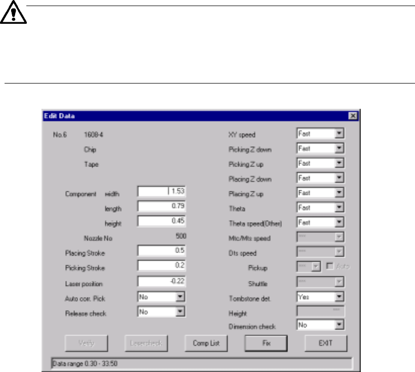
6.4.13 Editing data
You can modify some part of data created on the Component data screen (such as
component dimensions and laser height) without quitting the "PWB production" screen.
Therefore, you can edit data while maintaining the continuous production status which
allows you to abort production.
If you want to change items not provided with the <Edit> button, terminate the current
production, then edit the production program. Note that you cannot resume the
continuous production and you have to start production newly.
You can invoke this editing data function from the men bar before
production starts: by selecting [Tool] command, then [Operation option]
command, or invoke it when production pauses (because the stocked
components run out, laser recognition error occurs, tombstone error occurs
or so on).
Figure 6.4.13.1 Edit Data dialog box