KE2010.Instruction Manual.Ver.2.01,Rev.08.pdf - 第559页
7 − 22 − Press the F9 k ey or click the r ight but ton of the track ball to st art up the Mechanical Setup wi ndow . Then, set the “Suppor t plate” t o ON. Figure 7.2.2. 3.2 − During teaching , the f ollowing “Quest ion”…
7 − 21
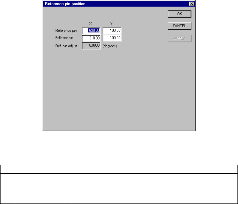
7.2.2.3 Reference pin position
A screen appears as shown in Figure 7.2.2.3.1 “Reference pin position setting
dialog box” when [Reference pin position] is selected from the [Setting Group]
menu.
Figure 7.2.2.3.1 Reference pin position setting dialog box
(1) Setting items
No. Item Description
1 Reference pin (X, Y) Reference pin position
2 Follower pin (X, Y) Follower pin position
3 Ref. pin adjust Board filting angle calculated based on the positions of the reference pin and
the follower pin (for automatic operation only)
(2) How to set
− Key in X and Y coordinate values directly from the keyboard.
− Use the HOD to teach and enter the coordinates. In this case, both the X
and Y values are entered at the same time if either X or Y is in focus.
When the X or Y of the reference pin is in focus, the values will be used for
the reference pin. When t-he X or Y of the follower pin is in focus, the
values will be used for the follower pin.
− Follow the procedure below to raise the support plate before teaching.
7 − 22
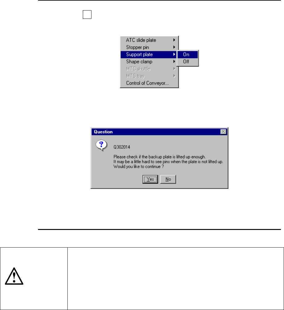
− Press the F9 key or click the right button of the track ball to start up the
Mechanical Setup window. Then, set the “Support plate” to ON.
Figure 7.2.2.3.2
− During teaching, the following “Question” message appears on the screen.
Figure 7.2.2.3.3
− When the support plate is raised, click the <Yes> button.
CAUTION
To avoid a risk of injury, do not place your hand in the machine, nor
move your face or head close to the machine during operation of the
HOD.
If you are to produce PWBs based on the reference pin, be sure to
check the setting of the item "Reference pin" above. If the reference
pin is not set before a PWB is fed, the "Reference pin error" is
displayed on the screen.
7 − 23
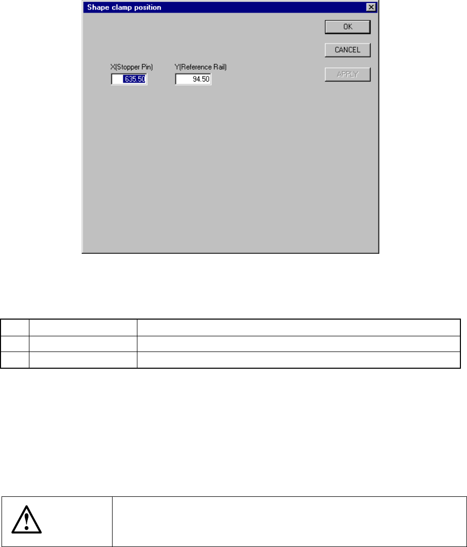
7.2.2.4 Shape clamp position
A screen appears as shown in Figure 7.2.2.4.1 “Shape clamp position setting dialog
box” when [Shape clamp position] is selected from the [Setting Group] menu.
Figure 7.2.2.4.1 Shape clamp position setting dialog box
(1) Setting items
No. Item Description
1 X Stopper pin position
2 Y Reference board transport rail position
(2) Setting the position
− Key in X and Y coordinate value directly from the keyboard.
− Use the HOD to teach and enter the coordinates for X and Y separately. In
this case, if X is in focus, only X is taught, then stored.
− To teach Y, Y shall be in focus.
CAUTION
To avoid a risk of injury, do not place your hand in the machine, nor
move your face or head close to the machine during operation of the
HOD.