KE2010.Instruction Manual.Ver.2.01,Rev.08.pdf - 第284页
4 – 177 Figure 4.1 1.1.5 Component data pop-up menu (f or a bulk) Figure 4.1 1.1.6 Component data pop-up menu (for a stick) Figure 4.1 1.1.7 Component data pop-up menu (for a stick changer) Figure 4.1 1.1.7a Component da…
4 – 176
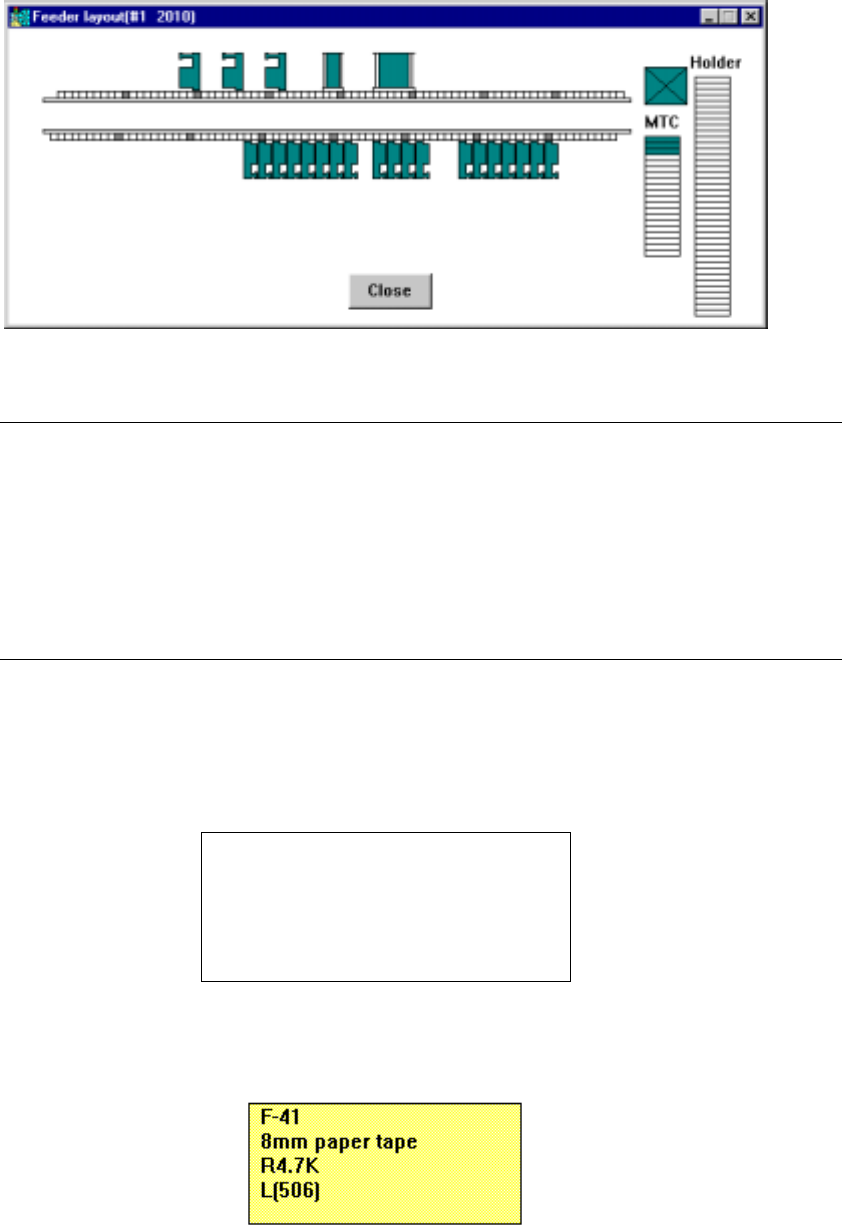
1. Feeder layout window
An example of the feeder layout window is shown below.
Figure 4.11.1.2 Example of the Feeder layout window
Note: On the Feeder layout window, displayed are various feeders and trays whose
component feeding positions are specified in Pick data List screen. Feeders
and trays whose “Tray Feeder” or “Sply” item is set to “Auto” are not displayed
on this window.
When you click the <Close> button on the Feeder layout window, this window
closes.
When you press the ALT and F4 keys of the keyboard at the same time, this
window closes also.
(1) When you move the cursor over the figure of a feeder on the Feeder layout
window with a trackball, part of the Component data associated with the feeder
appears on the screen as a pop-up menu.
Feeder mounting position
Feeder type
Component name
Centering method (nozzle number)
Lane number
Figure 4.11.1.3 General format of component data pop-up menu
Figure 4.11.1.4 Component data pop-up menu (for a feeder)
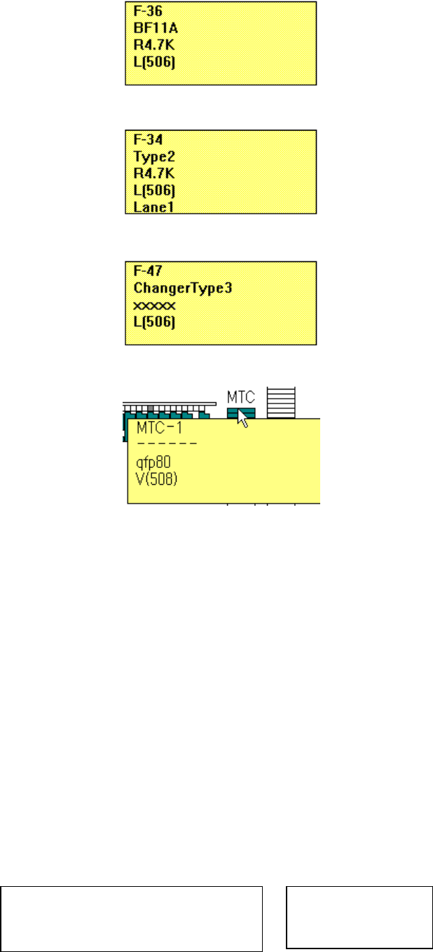
4 – 177
Figure 4.11.1.5 Component data pop-up menu (for a bulk)
Figure 4.11.1.6 Component data pop-up menu (for a stick)
Figure 4.11.1.7 Component data pop-up menu (for a stick changer)
Figure 4.11.1.7a Component data pop-up menu (for an MTC)
All centering methods (nozzle numbers) which are specified in Component data
are displayed. Although the centering method (nozzle number) which cannot
be handled depending on a model name may displayed, the centering method
and nozzle number which can be handled with the model are assigned to the
model if you perform the Optimization utility.
If there is no centering method/nozzle number which can be handled with the
model, the machine performs the line coherence check to find the appropriate
ones.
For an MTC and tray holder, with a trackball, move the cursor over the
appropriate MTC/tray holder shown on the right side of the figure displayed on
the "Feeder layout" window.
(2) When an IC collection belt is optionally installed on the machine, the following
pop-up men appears on the screen.
Figure 4.11.1.8 General format and example of the
Component data pop-up menu
IC collection belt mounting position
IC collection belt
R-71
IC collection belt
4 – 178
If any feeder is designated at the IC collection belt position, the displayed figure
indicates that the IC collection belt is overlaid by the feeder. If the Optimization
utility cannot prevent such an overlaying, an error occurs. Specify the feeder
position so that the IC collection belt cannot be overlaid by the feeder.
Even though you move or copy a feeder over the IC collection belt, any error or
warning does not appear on the screen.
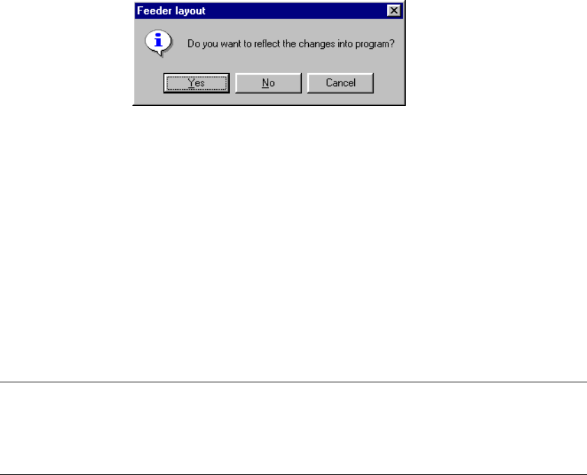
2. Editing data on the Feeder layout window
With a trackball, you can edit the feeder layout on the Feeder layout window.
When you edit the data, and click the <Close> button on the Feeder layout
window or Station chooser dialog box, the message appears on the screen
which asks you whether to save your edition in the program data.
(When you click the Feeder layout window with the left button of a trackball
even once, it is regarded as editing operation. The following message appears
on the screen.)
Figure 4.11.1.9 Update confirmation message
• Yes: saves changes in the program data, then Pick data is changed.
The coordinates of a pick point moved or copied are reset to the
designed values.
• No: Discards changes.
• Cancel: Returns to the state of the machine before you click the <Close>
button.
Each edit function is described below.
Note: An IC collection belt cannot be edited.
Editing data on the Feeder layout window is performed by modifying a
displayed figure with a trackball in the manner you edit Pick data with a
keyboard, for example to edit the feeder mountable area.