KE2010.Instruction Manual.Ver.2.01,Rev.08.pdf - 第208页
4 – 101 4.7.8 List w indow On the List window , t he summar y of two or more Com ponent data pieces is displayed in the f orm of a list on the scr een. T o display this List window , select the menu it em [Component list…

4 – 100
⑤
SOT Angle
Check the radio button to decide whether to check the SOT direction.
You can check this radio button only if “SOT” is selected as the component type.
When you check the radio button “Yes”, the system checks the direction of an
SOT component if the divide destination station can check a component.
Note: For a component having leads, be careful to enter the standard size
(“Std.size”). As the component size, specify the length and width (including
the tip of a lead) normally. The standard size to be specified in the “Std. Size”
field of the “Dimension check” section is the horizontal and vertical dimensions
of a surface on which a laser beam impinges.
4 – 101
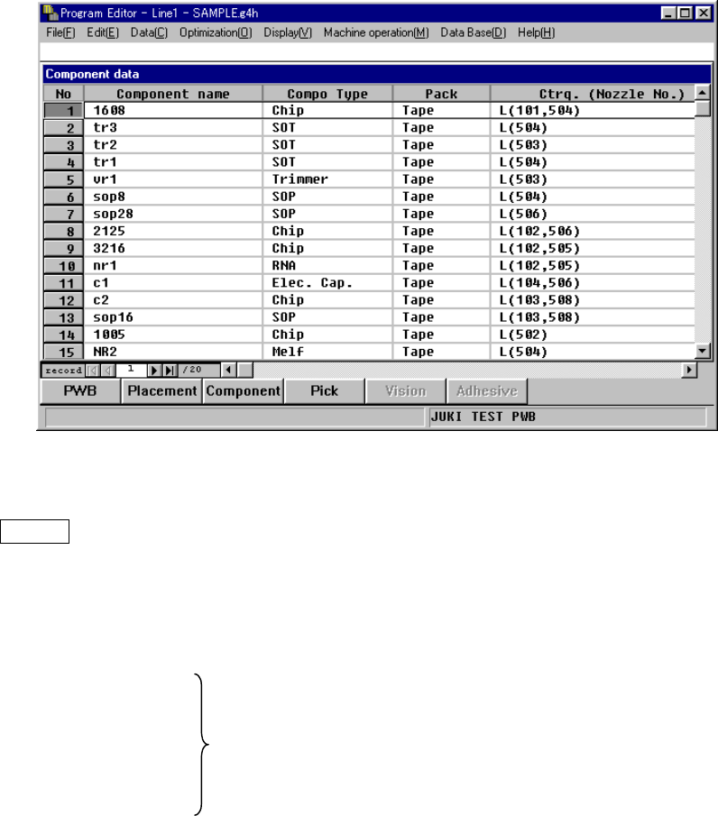
4.7.8 List window
On the List window, the summary of two or more Component data pieces is displayed
in the form of a list on the screen. To display this List window, select the menu item
[Component list] on the Display (V) menu while the Component form window is being
displayed on the screen.
On the List window, you cannot enter any data, but can check how much data has
been created. When you move the Highlight cursor to the desired data and press
ENTER key or double-click it, you can move to the Form window of the selected
Component data.
When you select the [Component form] menu item on the “Display (V)” menu, you
can return to the Form window also.
Component Name
Compo Type
Pack The same values as those set on the Form window are displayed.
Feeder Type
Centering (Centering)
Place (Adhe) This field shows the number of components to be mounted. The
value in parentheses represents the number of components to
be coated among them.
Feeder This field indicates the number of feeders (stick and tray
feeders) which feed the components.
Layer This field shows the component layer.
Skip This field indicates if a component is to be skipped or not.
4 – 102
Tomb. This field shows whether a standing chip is detected.
Dim. (Dimensions) This field shows whether to execute the dimensions check.
Copla.(Coplanarity) This field shows whether to execute the coplanarity check.
Verify This field shows whether to execute the verify check. “Yes” is
displayed if the verify check is to be executed. “No” is
displayed if not.
Comp (Component) Represents the level of completion of Component or Pick data
Pick on the applicable component. “OK” indicates that Component
or Pick data is created completely, while “NG” indicates that
such data is not created completely.
Vision
Adhe (Adhesive)
L
An asterisk mark is displayed in the column for the
unavailable functions.
Pattern Name