KE2010.Instruction Manual.Ver.2.01,Rev.08.pdf - 第244页
4 – 137 (3-3) Coher ence check item s: error conditions Data ty pe Item Error conditions Pick-up of vision components The FM LA head (R head for a KE-2020, L and R heads for KE-2040) is set to “Not used” in Pick data of …
4 – 136
Data type Item Error conditions
Component data and
component pick-up position
data (for a KE-2030)
If the “Parallel Mode” is selected at the menu item “2030
Mode Specification” of the “2000 Option” tab, and “Use
manual station/position assignments” is selected at the menu
item “Pick Data” of the “Assignments” tab of the
“Optimization” menu, the machine checks to see if the
component pick-up position specified on Pick data is
consistent with that of each corresponding component data
record.
<Error conditions of Pick data associated with Component
data>
Component layer
(for a KE-2030)
If the “Sequential and Mix Mode” is selected at the menu item
“2030 Mode Specification” of the “2000 Option” tab, “Use
manual station/position assignments” is selected at the menu
item “Pick Data” on the “Assignments” tab, the component
pick-up position is specified at all of Pick data records, the
same layer number is assigned to the OUT station on
Placement data (see “Placement layer (for a KE-2030) of
Placement data) and the layers are not assigned in the order:
IN station and OUT station on Component data.
Maximum CL value on the IN side
≦
Minimum simultaneous
placement CL value
≦
Maximum simultaneous placement
CL value
≦
Minimum CL value on the OUT side
CL: Component layer number
Component
data
Use pick data/Not to use pick
data
If the pickup positions of all linked Pick data are specified and
“Not to use pick data” is selected at all Pick data (except the
case where all placement data linked to the corresponding
component are set to be skipped).
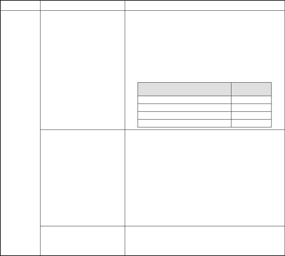
Component pick-up position
specified on Pick data
Consistency
check result
AUTO ○
Only one station
×
Only Both stations one station, AUTO ○
Both stations ○

4 – 137
(3-3) Coherence check items: error conditions
Data type Item Error conditions
Pick-up of vision components
The FMLA head (R head for a KE-2020, L and R heads
for KE-2040) is set to “Not used” in Pick data of vision
components.
*1
Placement of vision
components (over 0.4 mm)
(Lead components)
The standard VCS or optional VCS (37.5 mm, 27 mm or
18 mm) is not set in Placement data of vision
components whose size is 0.4 mm or larger.
*1
Placement of vision
components (0.3 <= Pitch < 0.4
mm) (Lead components)
The optional VCS (37.5 mm, 27 mm or 18 mm) is not
set in Placement data of vision components whose pitch
is 0.3 mm or wider, but narrower than 0.4 mm.
*1
Placement of vision
components (0.2 <= Pitch < 0.3
mm) (Lead components)
The optional VCS (27 mm or 18 mm) is not set in
Placement data of vision components whose pitch is 0.2
mm or wider, but narrower than 0.3 mm.
*1
Placement of vision
components (0.135 <= Pitch <
0.2 mm) (Lead components)
The optional 18 mm VCS is not set in Placement data of
vision components whose pitch is 0.135 mm or wider,
but narrower than 0.2 mm.
*1
Placement of general vision
components (15 < the smallest
pitch <= 22 mm) (Lead
components)
The standard VCS is not set in Placement data of
general vision components whose minimum pitch is
wider than 15 mm, but 22 mm or narrower.
*1
Placement of general vision
components (11 < the smallest
pitch <= 15 mm) (Lead
components)
The standard VCS or optional 37.5 mm VCS is not set
in Placement data of general vision components whose
minimum pitch is wider than 11 mm, but 15 mm or
narrower.
*1
Placement of general vision
components (6.5 < the smallest
pitch <= 11 mm) (Lead
components)
The standard VCS or optional 37.5 mm or 27 mm VCS
is not set in Placement data of general vision
components whose minimum pitch is wider than 6.5
mm, but 11 mm or narrower.
*1
Placement of general vision
components (0.5 <= the
smallest pitch <= 6.5 mm)
(Lead components)
The standard VCS or optional 37.5 mm, 27 mm or 18
mm VCS is not set in Placement data of general vision
components whose minimum pitch is 0.5 mm or wider,
but 6.5 mm or narrower.
*1
Placement of general vision
components (0.4 <= the
smallest pitch < 0.5 mm) (Lead
components)
The optional 37.5 mm, 27 mm or 18 mm VCS is not set
in Placement data of general vision components whose
minimum pitch is 0.4 mm or wider, but narrower than 0.5
mm.
*1
Placement of general vision
components (0.3 <= the
smallest pitch < 0.4 mm) (Lead
components)
The optional 27 mm or 18 mm VCS is not set in
Placement data of general vision components whose
minimum pitch is 0.3 mm or wider, but narrower than 0.4
mm.
*1
Placement of general vision
components (0.2 <= the
smallest pitch < 0.3 mm) (Lead
components)
The optional 18 mm VCS is not set in Placement data of
general vision components whose minimum pitch is 0.2
mm or wider, but narrower than 0.3 mm.
*1
Placement of vision
components (15 < the smallest
pitch <= 22 mm) (Ball
components)
The standard VCS is not set in Placement data of vision
components whose minimum pitch is wider than 15 mm,
but 22 mm or narrower.
*1
Placement of vision
components (11 < the smallest
pitch <= 15 mm) (Ball
components)
The standard VCS or optional 37.5 mm VCS is not set
in Placement data of vision components whose
minimum pitch is wider than 11 mm, but 15 mm or
narrower.
*1
Pick data
Placement of vision
components (6.5 < the smallest
pitch <= 11 mm) (Ball
components)
The standard VCS or optional 37.5 mm or 27 mm VCS
is not set in Placement data of vision components
whose minimum pitch is wider than 6.5 mm, but 11 mm
or narrower.
*1
*1: Items applicable to machines other than a KE-2010

4 – 138
Data type Item Error conditions
Placement of vision
components (1.0 <= the
smallest pitch <= 6.5 mm) (Ball
components)
The standard VCS or optional 37.5 mm, 27 mm or 18
mm VCS is not set in Placement data of vision
components whose minimum pitch is wider than 1.0
mm, but 6.5 mm or narrower.
*1
Placement of vision
components (0.8 <= the
smallest pitch < 1.0 mm) (Ball
components)
The optional 37.5 mm, 27 mm or 18 mm VCS is not set
in Placement data of vision components whose
minimum pitch is 0.8 mm or wider, but narrower than 1.0
mm.
*1
Placement of vision
components (0.5 <= the
smallest pitch < 0.8 mm) (Ball
components)
The optional 27 mm or 18 mm VCS is not set in
Placement data of vision components whose minimum
pitch is 0.5 mm or wider, but narrower than 0.8 mm.
*1
Placement of vision
components (0.35 <= the
smallest pitch < 0.5 mm) (Ball
components)
The optional 18 mm VCS is not set in Placement data of
vision components whose minimum pitch is 0.35 mm or
wider, but narrower than 0.5 mm.
*1
Placement of chip rise
detecting option components
The chip rise detecting unit is not available in Placement data
of the chip rise detecting option components.
Check of the maximum number
of components
The number of components exceeds the maximum number of
components which can be picked up.
Pick-up of vision components
(over 33.5 mm)
The standard VCS is not available in Pick data of vision
components whose dimension exceeds 33.5 mm.
*1
Pick-up of vision components
whose dimension is longer
than 24 mm, but 33.5 mm or
shorter.
The standard VCS or optional 37.5 mm VCS is not
available in Pick data of vision components whose
dimension is longer than 24 mm, but 33.5 mm or
shorter.
*1
Pick-up of vision components
whose dimension is longer
than 16 mm, but 24 mm or
shorter.
The standard VCS or optional VCS (37.5 mm, 27.5 mm
or 27 mm) is not available in Pick data of vision
components whose dimension is 23 mm or shorter.
*1
Pick-up of vision components
whose dimension is 16 mm or
shorter
The standard VCS or optional VCS (37.5 mm, 27.5 mm,
27 mm or 18 mm) is not available in Pick data of vision
components whose dimension is 14 mm or shorter.
*1
A coplanarity unit is enabled and a model earlier that
JVS4 is specified as the VCS in Placement data on
coplanarity option components.
*1
Pick-up of Coplanarity option
components
“Automatic selection” is selected, a coplanarity unit is
enabled and a model earlier than JVS4 is specified as
the VCS in Pick data on coplanarity option components.
*1
Pick-up of Verify option
components
The verify unit is not available in Pick data of verify option
components.
Overlap of IC collection belt
The feeder specified in Pick data is positioned over the
IC collection belt.
*1
The stick changer cannot be handled. Stick type
The number of stick changers exceeds the number of stick
changers installable.
If a stick changer is installed on the rear bank.
Component height 20 mm
The component height is not set to 20 mm in Pick data
of components whose height exceeds the standard
component height set for each station.
*1
Pick position
The system calculates the pick position of each component,
and checks to see if the calculated positions are within the
head axis movable area.
Pick data
Pick-up of general vision
components
If the specified vision processor unit is a model earlier than
JVS3 in the placement data on a general-purpose vision
component.