KE2010.Instruction Manual.Ver.2.01,Rev.08.pdf - 第204页
4 – 97 4.7.7 Tack control section (Inspection page) ① T ombstone det. Using the r adio button, select whether to use the chip r ise detecting opt ion. − W hen you select the radio button “ Y es” or “If possible,” enter t…
4 – 96
③
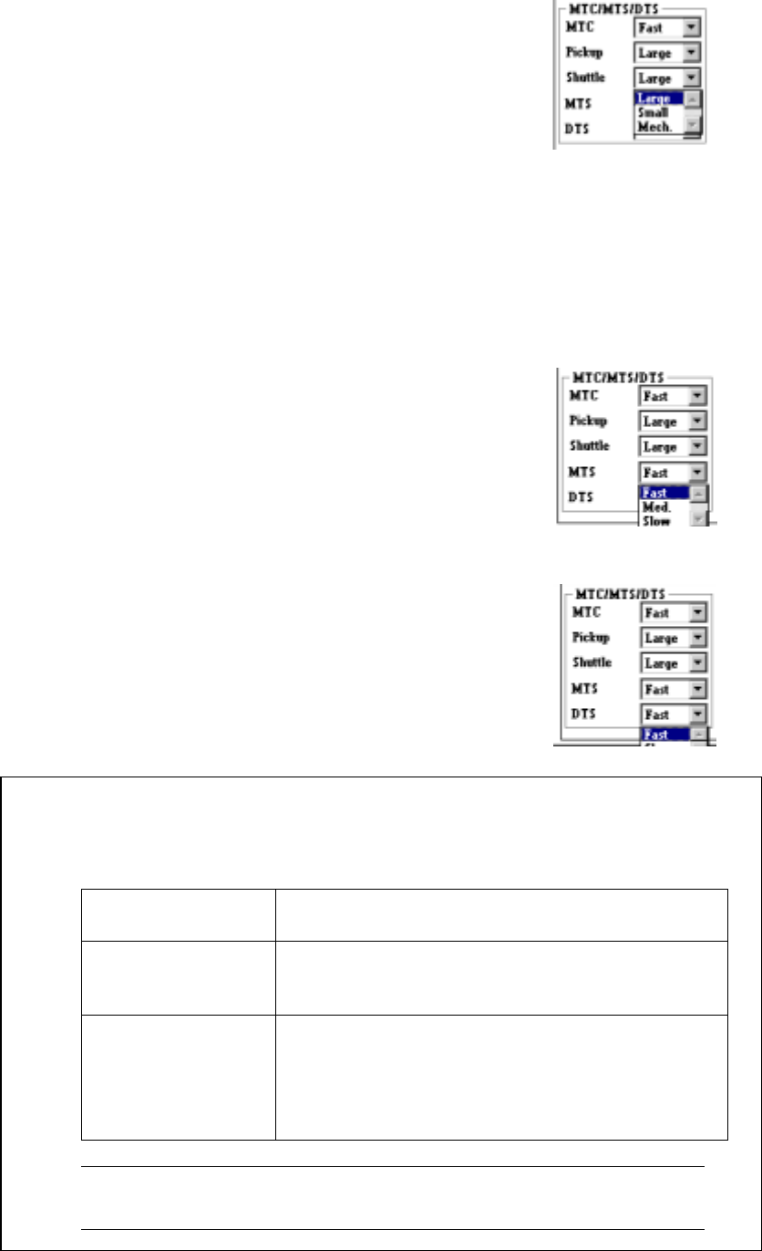
Shuttle
Specify the MTC shuttle pad type in the combo box.
• This setting allows you to select the pick-up
pad of the shuttle depending on a
component to be picked. (See Table 4.7.6
“Default values for a pick-up pad”.)
• When you select "Mech.", the machine
cannot return a component onto the MTC.
Select a choice other than "Tray restore" at
the control item "Compo Reject to"
displayed on the "Add Info." page of the
Tack Control section.
④
MTS
Specify the MTS speed in the combo box.
• Specify the speed for pulling out a tray here.
⑤
DTS
Specify the DTS speed in the combo box.
• Specify the speed for pulling out a tray here.
− The default values for a pick-up pad are shown in the table below.
Table 4.7.6 Default values for a pick-up pad
Display on the
screen
Default values
Pickup – When the shorter side of component dimensions
is less than 16 mm: Small
16 mm or more: Large
Shuttle – When the component type is BGA: Mech.
– When the component type is other than BGA,
and the shorter side of the component
dimensions is less than 16 mm: Small
16 mm or more: Large
Note: You may have to change the shuttle setting depending on the
lead length or component shape.
4 – 97
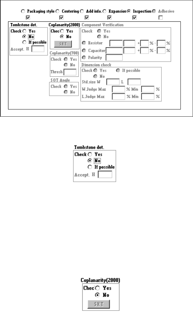
4.7.7 Tack control section (Inspection page)
①
Tombstone det.
Using the radio button, select whether to use the chip rise detecting option.
− When you select the radio button “Yes” or “If possible,” enter the “Accept. H”
filed.
− If you select “If possible”, the machine detects a chip rise error when the chip
rise detecting unit is installed on the machine.
②
Coplanarity (featured in KE-2020 / 2040 only)
Specify whether to check if a lead of a component floats or not with using the
radio button.
− When you check the radio button “YES”, the <Set> button is enabled.
Enter the coplanarity check data.
4 – 98
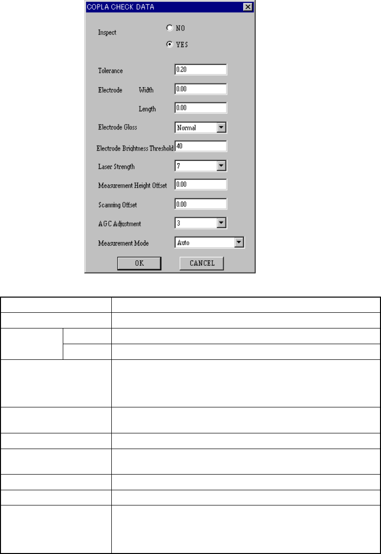
When you click the <Set> button, the following “COPLA CHECK DATA” dialog
box appears on the screen.
Inspect Select whether to perform the coplanarity check or not.
Tolerance Set the value used for judgment.
Width Set the width of the electrode. Electrode
Length Set the length of the electrode.
Electrode Gloss
Set the electrode coating information.
• Normal
• Glossy
• Not glossy
Electrode Brightness
Threshold
Set the threshold value for the brightness of a electrode.
Laser Strength Set the laser strength.
Measurement Height
Offset
Set the offset for the measured height.
Scanning Offset Set the offset for the scanned position.
AGC Adjustment Set the AGC corrected value.
Measurement Mode
Set the measurement mode:
• Auto
• Normal measurement mode
• High-precision measurement mode
Click the <OK> button to validate your settings, or <CANCEL> button to cancel
your settings.
For BGA and FBGA component, it is impossible to set the electrode width and
length, electrode gloss information, and scan position offset value.