KE2010.Instruction Manual.Ver.2.01,Rev.08.pdf - 第681页
9 − 27 (Referene) A Trouble that occurs i f you do not clean the stained l aser alignment sensor w indow ① Inappropr iate placement precision (A recog nition err or occurs if stains ar e located over the shadow of a comp…
9 − 26
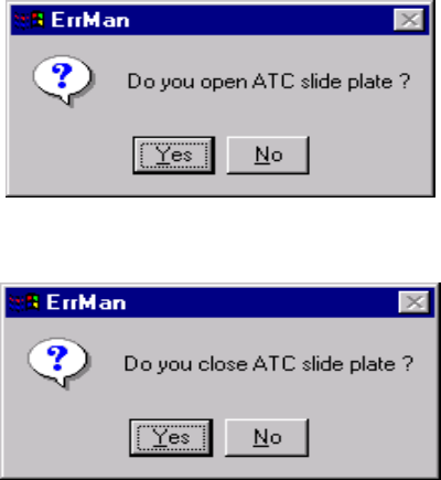
Step 2. When you click the <ATC Open>/<ATC Close> button on the screen shown
in Figure 9.5.1.2, the following confirmation dialog box appears on the
screen.
Figure 9.5.1.2.3 <ATC Open> confirmation screen
Figure 9.5.1.2.4 <ATC Close> confirmation screen
9.5.1.3 Checking to see if the laser alignment sensor window is stained
When the laser sensor window is stained, be sure to clean it.
Step 1. Clean the laser alignment sensor window.
See Section 13.3.3”Laser Alignment Sensor” of Chapter 13
“MAINTENANCE” for how to clean the laser alignment sensor window.
Step 2. Check to see if the laser alignment sensor window is not stained after
cleaning it.
Press the <Edge Disp> button on the “Nozzle On Head Information” dialog
box shown in Figure 9.5.1.
Clean the laser alignment sensor window until the displayed value gets
below the threshold displayed in red.
The Manual Control utility allows you to check the more detailed
information.
(See Section 8.2.3 “Laser Control” of Chapter 8.”)

9 − 27
(Referene)
A Trouble that occurs if you do not clean the stained laser alignment
sensor window
① Inappropriate placement precision (A recognition error occurs if stains are
located over the shadow of a component. Therefore, the machine may
not realize the regulated placement precision randomly.)
② Incensement of the number of discarded components (due to a
tombstone error, component dimension error and component orientation
error as well as laser error)
③ Lowered cycle time (because a laser recognition retry operation should
be performed)
④ Nozzle replacement error (because a nozzle is recognized with laser)
B Reason why the laser alignment sensor window is stained
The laser alignment sensor window may be stained due to dust, oil (oil of the
compressor and grease applied to the head are scattered), or dried-up
dust-like solder paste.
− Oil of the compressor:
See Section 13.2.1 “Air pressure” of Chapter 13 “MAINTENANCE”.
If oil or water is stored in the drain, remove it.
− Cleaning a nozzle:
See Section 13.3.4 “Nozzle” of Chapter 13 “MAINTENANCE” for how to
clean a nozzle.
<
<<
<Checkpoint>
>>
>
① Check to see if the Z-slide shaft section is greased too much.
② Check to see if any solder paste is stuck to a tip of a nozzle. If you judge
that a nozzle is not in contact with any solder paste on a board, solder
paste sprayed with air may piles at the tip of a nozzle little by little.
In such a case, check to see if:
• The pitch of a feeder is shifted, or
• The used nozzle is too large for a component.
9 − 28
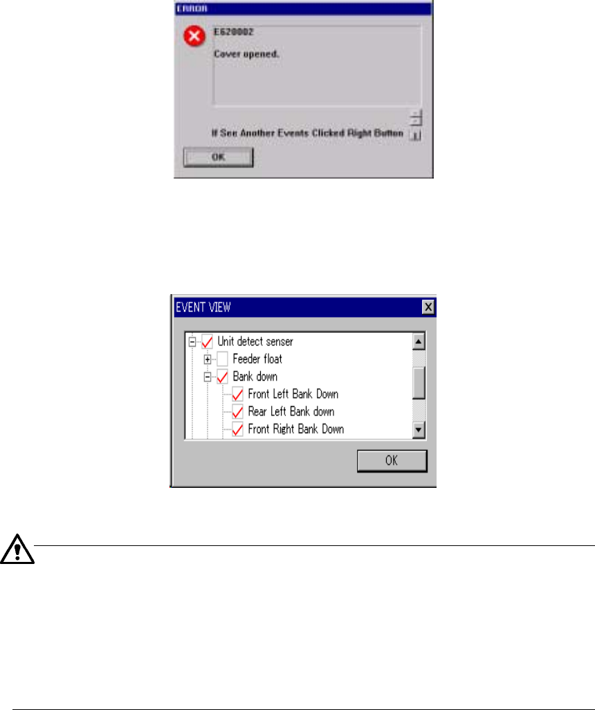
9.5.2 Event View buttons
The following screen appears if you open the safety cover, if you press the
Emergency Stop button, or if the machine detects an alarm of each axis servo driver.
− The message “If See Another Events Click Right Button” may appears on the
screen. This message appears if two or more events occur at the same time,
and the machine can display the event whose priority is higher only on the screen.
Figure 9.5.2.1 “ERROR” screen
When you click the <OK> button, events are displayed in the hierarchical view.
A check mark is displayed next to the events that actually occurred.
Figure 9.5.2.2 Hierarchical display of events
You do not have to check the events on the hierarchical display above normally.
However, if a driver error occurs and you judges the machine malfunctions, check this
display.
If a driver alarm error appears on the screen, check to see if an event that turns off
the servo power supply (such as Emergency Stop, area sensor activation, feeder float
and so on) occurs. If an event that turns off the servo power supply occurs even
though a driver alarm error appears on the screen, a driver may not malfunction in
many cases.