KE2010.Instruction Manual.Ver.2.01,Rev.08.pdf - 第502页
6 − 126 ③ Ret urning a component af ter check ing it The system ret urns some check ed components ont o their orig inal positions, or discards other ones depending on their pack aging style as shown in Table below (6.7.1…
6 − 125
6.7 Checking
After a component is attached on a head, use each hardware device to perform
various types of inspection.
− After selecting the [Tool] command on the Production dialog box, and then the
[Check] command on the “Tool” menu, select the check item on the sub-menu.
Main
menu
Pull-down
menu
Sub-menu Description
Verify Current check Performs a single verification check. *1
1
Verify All check Performs a continuous verification check. *1
2 Laser height check Performs a laser height check.
SOT Current check Performs a single SOT check.
Tool Check
3
SOT All check Performs a continuous SOT check.
*1 Optionally set at the factory.
6.7.1 Single Verification Check/Continuous Verification Check (Optional)
This function is optional and set at the factory.
6.7.1.1 Verification checking function
Two modes: “Continuous check mode” and “Single check mode” are provided,
and functions available in each mode are described below.
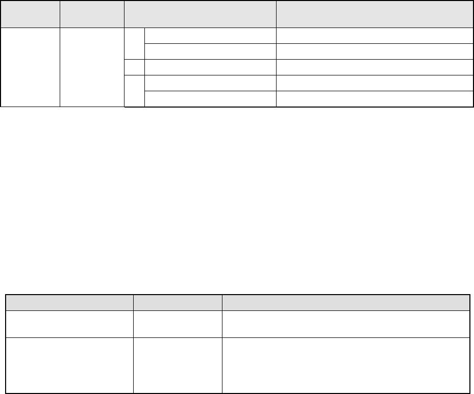
Table 6.7.1.1 Check mode and its menu
Tool menu Operation mode Description
Verify Current check Single check Checks each component that caused an error in
Continuous verification mode.
Verify All check Continuous check Checks all components or components that satisfy the
requirements you set in a production program.
◆ In Single mode, the machine can check a component
that failed to be inspected.
6.7.1.2 Operations
①
Head used to pick up a component
The system automatically selects a head that is used to pick up a component.
The system selects and uses a nozzle already attached on a head rather than
one not attached so that the frequency of nozzle replacement can be reduced.
However, the system may use a different head every time it measures a
component depending on the nozzle attachment condition.
②
Applicable components
The system checks a square chip only.
6 − 126
③
Returning a component after checking it
The system returns some checked components onto their original positions, or
discards other ones depending on their packaging style as shown in Table
below (6.7.1.2). Where to discard a component is determined according to the
setting of “Compo Reject to” on the Component data screen. The system
discards a checked component when the menu item “Compo Reject to” is set to
“Trash conveyor” or “Protect.”
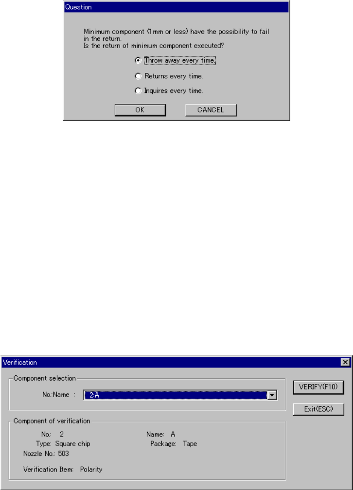
− Since a component whose size is 1 mm or less may stand on its side or
may be turned upside down when it is returned to the original position, the
system displays the “Question” dialog box shown in Figure 6.7.1.2.1 to ask
you how it should handle a component.
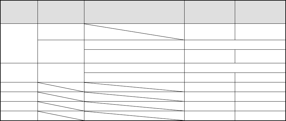
Table 6.7.1.2 Requirements for returning/discarding a component
Packaging
style
Requirement 1 Requirement 2 When
returning a
component
When
discarding a
component
32-mm tape
feeder
− ○
The shorter side is 1 mm or shorter. Question dialog box *1
Tape
Tape feeders
other than the
above
The shorter side is 1 mm or longer. ○ ○ *2
The shorter side is 1 mm or shorter. Question dialog box *1
Bulk −
The shorter side is 1 mm or longer. ○ ○ *2
Holder ○ ○ *2
MTC ○ ○ *2
MTS ○ ○ *2
Stick − ○
*1 The system displays the dialog box to prompt you to select whether to return or
discard a component. When the system is set to measure components
continuously, it displays the dialog box at start of continuous measurement.
*2 The system discards a checked component when the menu item “Compo Reject
to” is set to “Trash conveyor” or “Protect.”
④
Selecting a feeder used to pick a component
If tow or more feeders are assigned to the same type of components on the
Pick data screen, the system starts picking up components from one whose
data was entered first of all by default.
Only in Single check mode, you can change the feeder used to pick up a
component intentionally (see Figure 6.4.4.3.2).
⑤
Changing the coordinates of a component pick-up position
When a component is not picked up properly, manually enter the coordinates or
use the HOD device to teach them to change the coordinates of a component
pick-up position.
6 − 127
⑥
Manual pick-up
If there is no Pick data, you can attach a component on a nozzle manually. In
such a case, you cannot enter any coordinate of a component pick-up position.
You cannot operate any feeder either.
Figure 6.7.1.2.1 “Question” dialog box
6.7.1.3 Single verification check
6.7.1.3.1 “Verification” component selection dialog box
When you select the [Tool] command from the menu bar, the [Check] command on
the “Tool” menu, and the [Verification] command on the Production menu, the
following dialog box appears on the screen.
− The “NO.:Name” combo box lists square chips whose menu item “Verify” is set
to “Yes” on the Component data screen.
− Select a component to be checked.
Figure 6.7.1.3.1 “Verification” single check component selection dialog box