KE2010.Instruction Manual.Ver.2.01,Rev.08.pdf - 第496页
6 − 120 (2) Manual run W hen "Manual" is selected in the "Pick track ing" f ield, t he monitoring camera moves over the first point of pickup after trial r un, shoots the picked up component, outputs …
6 − 119
To cancel the pause status, press the <START> or <STOP> switch. When
the <START> switch is pressed, monitoring by camera restarts immediately.
When the STOP switch is pressed, monitoring by camera terminals and a
dialog box for confirmation appears.
② Changing a pickup point
When the machine is in the stop status, the pickup point can be taught by the
CAMERA key of the HOD.
It is also possible to change the pickup point directly by numeric keys on the
ten-key pad.
- The value to be entered manually is the value displayed on the screen ±3
mm.
The head starts moving when you enter the coordinates and press the
<SET> button.
③ Returning to the previous pickup point
When the machine is in the pause status, you can return to the previous
pickup point by pressing the PREVIOUS key of the HOD.
The pause status is still held even after the camera returns to the previous
pickup point.
④ Going to the next pickup point
In the pause status, you can go to the next pickup point by pressing the
NEXT key of the HOD.
The pause status is held even after the camera goes to the next pickup point.
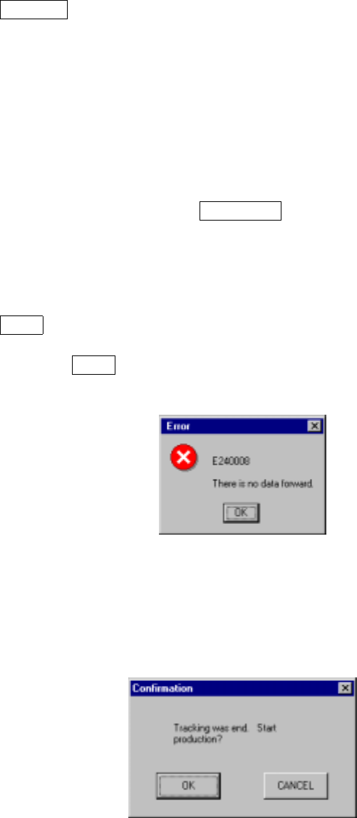
When the NEXT key is pressed again at the last pick point, the following
message box appears to tell the operator that that is the last tracking point.
Figure 6.5.4.2 Last tracking position message box
When the <START> switch is pressed at the last pick point, the following
dialog box (Figure 6.5.4.3) appears and the operator is asked whether to
enter Production mode.
Figure 6.5.4.3 "Tracking was end." dialog box
6 − 120
(2) Manual run
When "Manual" is selected in the "Pick tracking" field, the monitoring camera
moves over the first point of pickup after trial run, shoots the picked up component,
outputs it to the monitor screen, and pauses there.
The pause screen for "Manual" is the same as that for "Automatic".
(3) Subjects of pick camera tracking and tracking order
Pickup tracking is performed from No.1 to No.60 at the left front, from No.60 to
No.1 at the left rear, then the right station in this order.
Any pick points used for pick data are subject to tracking operation regardless of
the range of trial run (specified placement points/components).
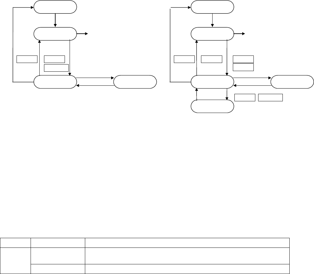
(4) Operation mode
The following chart shows the mode transition in the operation mode.
①
For manual tracking
②
For automatic tracking
Condition setting
One point tracking
START switch
Production starts.
Pause
STOP
switch
START
switch
CANSEL NEXT
PERVIOUS
Movement finishes.
HOD device key
Teaching completes.
Teaching
Condition setting
One point tracking
START switch
Production starts.
Pause
STOP
switch
START
switch
CANSEL NEXT
HOD device key
Teaching completes.
Teaching
STOP
switch
PAU SE
CANSEL
One point tracking
Movement finishes.
NEXT
PERVIOUS
- Information of vision camera
The following two types of data are displayed on the vision camera
① Raw image at pick points
② Cursor (Crosshair or window cursor)
The size of the window cursor displayed here is the same as the size of
components. For large components which cannot be viewed with the vision
camera or for the components with which the window cursor cannot be used
because their pick angle is not a multiply of 60 degrees, the crosshair cursor
is used instead of the window cursor.
Conditions for displaying information on the vision camera screen
Item Type Conditions
Crosshair cursor For the components whose pick angle is neither 0
°
, 90
°
, 180
°
nor 270
°
,
or whose dimensions is more than 5.00 mm.
Cursor
Window cursor For the components whose pick angle is 0
°
, 90
°
, 180
°
or 270
°
.

6 − 121
6.6 Blank Run
When you select the [Production conditions] command from the menu bar, then the
[Dry Run] command on the displayed menu, the "Dry Run conditions" menu appears
on the screen.
(1) Setting items
No. Item Description
1 Setting items
selection
Switch the dialog box to be displayed on the screen among: Production
conditions dialog box, Trial Run conditions dialog box, and Dry Run conditions
dialog box.
2 Prod. PWB Set the number of boards for blank run.
3 Sequence Select the order of placement sequence: the input order or Opt. (optimized)
order.
4 Exec. mode Select continuous production or step-by-step production.
5 Placement ofs. Designate offset for all placement positions. This offset is added to the
placement positions for actual component placement.
6 Step No. Designate the start line number and the end line number of the range of the
placement data in the input order.
When "Opt. order" is selected as the "Sequence", the start and end line
numbers are handled as the optimized data numbers also.
7 Place tracking After blank run of a board, designate whether or not to perform placement
tracking by the camera. If performed, set whether it is manual or automatic.
Off: Placement tracking is not performed.
Automatic: Placement tracking is performed automatically.
Manual: Stops at each placement position, and then goes to the next
placement position through a key-in by the operator.
8 Pick tracking Before blank run of a board, designate whether or not to perform pickup position
tracking by the camera. If performed, set whether it is manual or automatic.
Off: Pickup tracking is not performed.
Automatic: Pickup tracking is performed automatically.
Manual: Stops at each placement position, and then goes to the next
pickup position through a key-in by the operator.
9 Automatic interval When camera tracking is performed automatically, designate the waiting time
duration at a stop position. (time duration in 10 msec: "1" indicates "10 msec")
Note: The value specified on the Operation option menu is displayed at the item
"Reference pin correction", and cannot be changed on this dialog box.