KE2010.Instruction Manual.Ver.2.01,Rev.08.pdf - 第42页
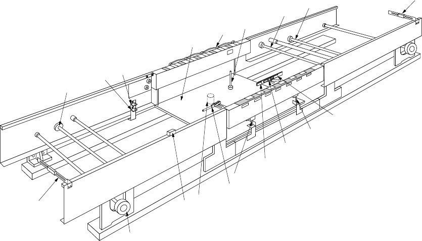
1 − 25 Figure 1.2.2. 1 ① IN sensor ⑨ Stopper ② OUT sensor ⑩ Pusher X ( Edge refer ence option) ③ STO P sensor ⑪ Centering pin ④ C-OUT sensor ⑫ BU table ⑤ BU-UP sens or ⑬ Motor cont rol ⑥ BU-DOW N sensor ⑭ BU pin ⑦ PW B t…
1 − 24
1.2.2 PWB transfer unit: mechanism and parts identification
1. Pin reference
1) When a board is carried in and the IN sensor ① detects the board, the PWB
transport motor ⑦ drives the drive shaft ⑧ to start transporting the board
with the PWB transport belt. At the same time, the stopper ⑨ is turned on.
2) When the board reaches the stopper ⑨, the STOP 3 sensor detects it, then
the BU plate ⑫ moves up. The board is fixed with the centering pin ⑪ and
BU pin ⑭ which are attached on the BU plate ⑫.
3) After the board is fixed, the next board is carried in the same manner, and it
waits at the Wait sensor ⑯.
4) After production finishes, the fixed board is released, then the machine starts
ejecting it.
5) When the first board passes the C-OUT sensor ④, the stopper is turned on
again and the next board is fixed.
2. Edge reference <Optional>
The board transfer mechanism is the same as that of the pin reference above.
When the board is fixed, edges of the boards are held by the stopper ⑨ pusher,
X ⑩ (in the X direction) pusher, ⑮ (in the Y direction) and BU pin ⑭.
The transfer operation that follows is also the same as that of the pin reference
above.
1 − 25
Figure 1.2.2.1
①
IN sensor
⑨
Stopper
②
OUT sensor
⑩
Pusher X (Edge reference option)
③
STOP sensor
⑪
Centering pin
④
C-OUT sensor
⑫
BU table
⑤
BU-UP sensor
⑬
Motor control
⑥
BU-DOWN sensor
⑭
BU pin
⑦
PWB transport motor
⑮
Pusher Y (Edge reference option)
⑧
Drive shaft
⑯
Wait sensor
①
⑦
⑯
⑬
⑩
⑪
③
⑨
⑪
④
②
⑧
⑧
⑭
⑮
⑫
⑤
⑥
⑧
1 − 26
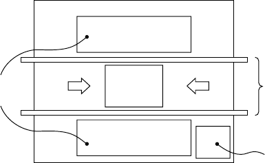
1.2.3 Component feeder
Totally two component feeder banks are provided: one bank is located at the front
and rear of the PWB transport unit respectively. The component supply method
varies depending on the package style of components: tape, bulk, stick or tray.
Components fed by a tape (chip components) or those fed in a stick are mounted on
the feeder bank with using a tape feeder, bulk feeder, stick feeder or stacked stick
feeder, then carried in the main unit. A tray component is fed from a tray holder,
matrix tray changer, or matrix tray server. A tray holder, matrix tray changer or
matrix tray server.can be mounted on the rear of the machine.
When using an overall feeder exchange trolley (option), the feeder bank can be
removed from the main unit of this machine for preparation.
(
)
Figure 1.2.3.1
Feeder banks
PWB
Vision monitor
Rear
Front
PWB transport unit