KE2010.Instruction Manual.Ver.2.01,Rev.08.pdf - 第576页
7 − 39 7.2.2.1 1 Multi -stati on line A screen appears as shown in Figure 7.2. 2.1 1. 1 “Multi-station line sett ing dialog box” when [M ulti-st ation line] is selected f r om the [Set ting G roup] menu. Figure 7.2. 2.1 …

7 − 38
- If you check the rear IC Conveyor belt on the "Option Device enable setting"
dialog box, you cannot set the MTS.
- Specify the menu item “Tray Pick Sequence” according to the following two
groups of units:
①Tray, DTs and MTS
②MTC
- Two types of orders in which tray components are to be picked are available:
click the corresponding radio button:
①Pick dir. 1 (Standard)
②Pick dir. 2 (X dir.)
Default: Pick dir. 1 (Standard)
- You can select either button regardless of the “disable”/”enable” setting of
the menu item “MTC”, “MTS”, or “DTS”.
- Even though the menu item “MTC” or the corresponding unit is set to
“disable”, you can set this menu item.
(3) Production operation
Table 7.2.2.10.5 Placement when set to "Unused"
No. Unit Production operation
1 MTC Components which are fed from the MTC are to be skipped.
2 MTS Components which are fed from the MTS are to be skipped.
3 DTS Components which are fed from the DTS are to be skipped.
Table 7.2.2.10.6 Placement when “Pick dir. 2 (X dir.)” is selected
No. Unit Production operation
1 Tray Starts picking up components from the start position (rear and far side)
toward the right direction when viewed from the front.
2 DTS Starts picking up components from the start position (rear and far side)
toward the right direction when viewed from the front.
3 MTS Starts picking up components from the start position (rear and far side)
toward the right direction when viewed from the front.
Pick-up order
MTC Starts picking up components from the start position (rear and far side)
toward the right direction when viewed from the front.
7 − 39
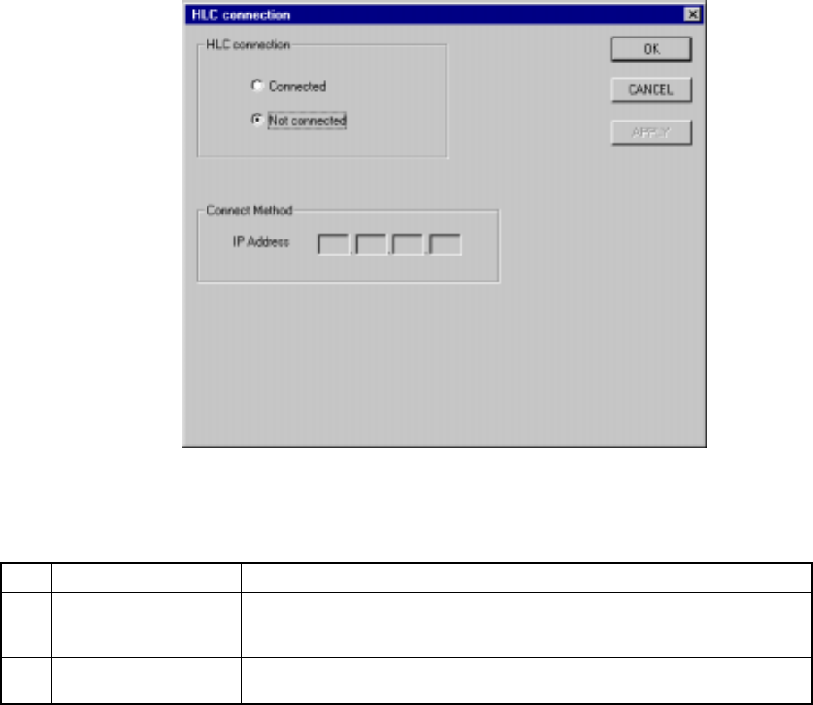
7.2.2.11 Multi-station line
A screen appears as shown in Figure 7.2.2.11.1 “Multi-station line setting dialog
box” when [Multi-station line] is selected from the [Setting Group] menu.
Figure 7.2.2.11.1 Multi-station line setting dialog box
(1) Setting items
No. Item Description
1 HLC connection This command is used to define whether or not this machine is connected to
an HLC in a multi-station line where two or more general purpose placers,
chip placers and bonding machines are connected to the HLC.
2 IP address Since the HLC and each station are to be communicated with each another
via the network, an IP address needs to be defined for each station.
(2) Setting the Multi-station line
① Connection to the HLC
− Using the radio button, define whether or not the machine is to be
connected to the HLC. (Default setting: Not connected)
② Connecting method (IP address)
− Each field of an IP address can be any number from 0 to 255. Two or
more stations cannot have the same IP address. Note that you cannot
set all fields to “0”.
− An IP address is a fixed number for the HLC.
− When “Connected” is selected with the “HLC connection” radio button,
set each field of an IP address to a value from 0 to 255. This dialog
cannot be closed when a number out of that range is set.
7 − 40
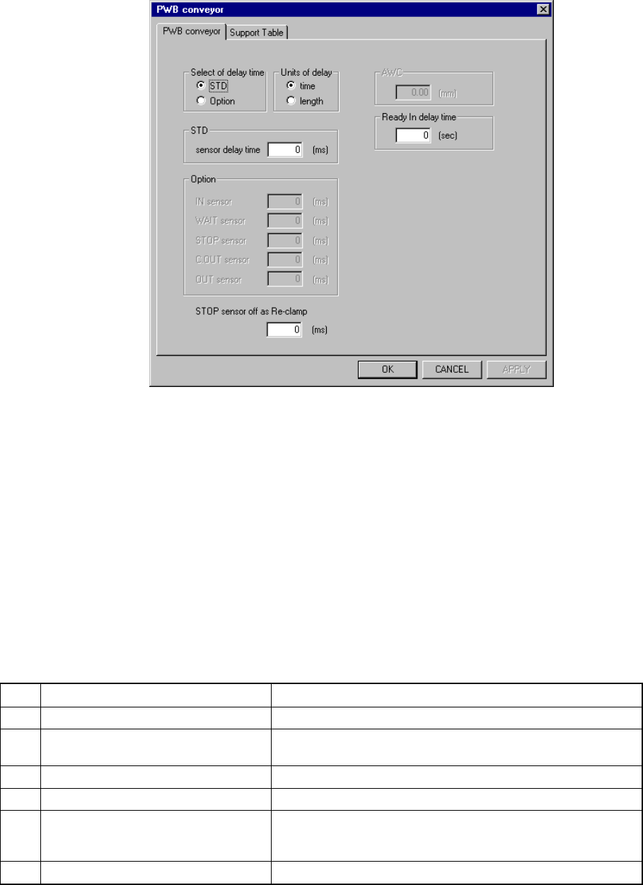
7.2.2.12 PWB conveyor
A screen appears as shown in Figure 7.2.2.12.1 “PWB conveyor setting dialog box”
when [PWB conveyor] is selected from the [Setting Group] menu.
Figure 7.2.2.12.1 PWB conveyor setting dialog box
When you click the corresponding tab, you can specify the PWB conveyor or
Support table.
7.2.2.12.1 PWB conveyor
When you select the [PWB conveyor] tab, the “PWB conveyor” dialog box shown
in Figure 7.2.2.12.1 appears on the screen. This dialog box appears also as the
initial screen displayed when you click the [PWB conveyor] command on the
“Setting Group” menu.
(1) Setting items
No. Item Description
1 Select of delay time Sets the method for setting the delay time of the sensor.
2 Units of delay Sets the unit used for the delay time of the sensor(s) specified
on the “PWB conveyor” tab.
3 STD Sets the delay time of all sensors.
4 Option Sets the delay time of an independent sensor.
5 STOP sensor off as Re-clamp Sets the time while the STOP sensor keeps being set to OFF
until the machine detects the OFF status of the STOP sensor
when a board is clamped again.
6 Ready In delay time Set the Ready In signal delay time.