KE2010.Instruction Manual.Ver.2.01,Rev.08.pdf - 第689页
10 − 5 10.3 Laser Sensor Height W hen y ou select the [ Set-up g roup] comm and on the menu bar , then select t he [Laser sensor heig ht] com mand on the displayed menu, t he following “Laser sensor height” dialog box ap…
10 − 4
− How to operate
When you follow the instructions displayed on the dialog box, the appropriate
values are automatically obtained.
Click the <Exec.> button.
When you click the <Exec.> button, the XY axes stop accuracy correction
parameters are automatically obtained.
− Measurement
① The machine obtains the temperature of the XY axes base frame, then
calculates the correction parameters.
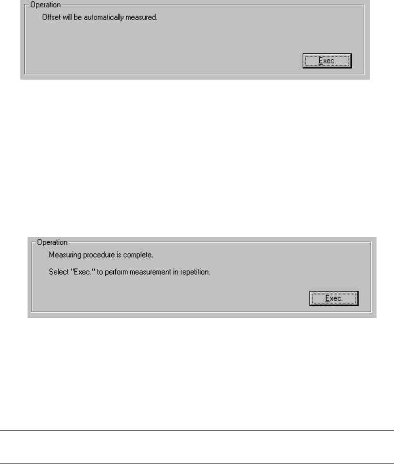
When calculation is done, the message above appears on the screen.
To repeat this calculation, click the <Exec.> button.
When you click the <Exec.> button, the previous screen reappears.
To exit from this dialog box, click the <OK> button.
Note: If you change the XY axes stop accuracy correction parameters, you have
to zero the XY axes.
10 − 5
10.3 Laser Sensor Height
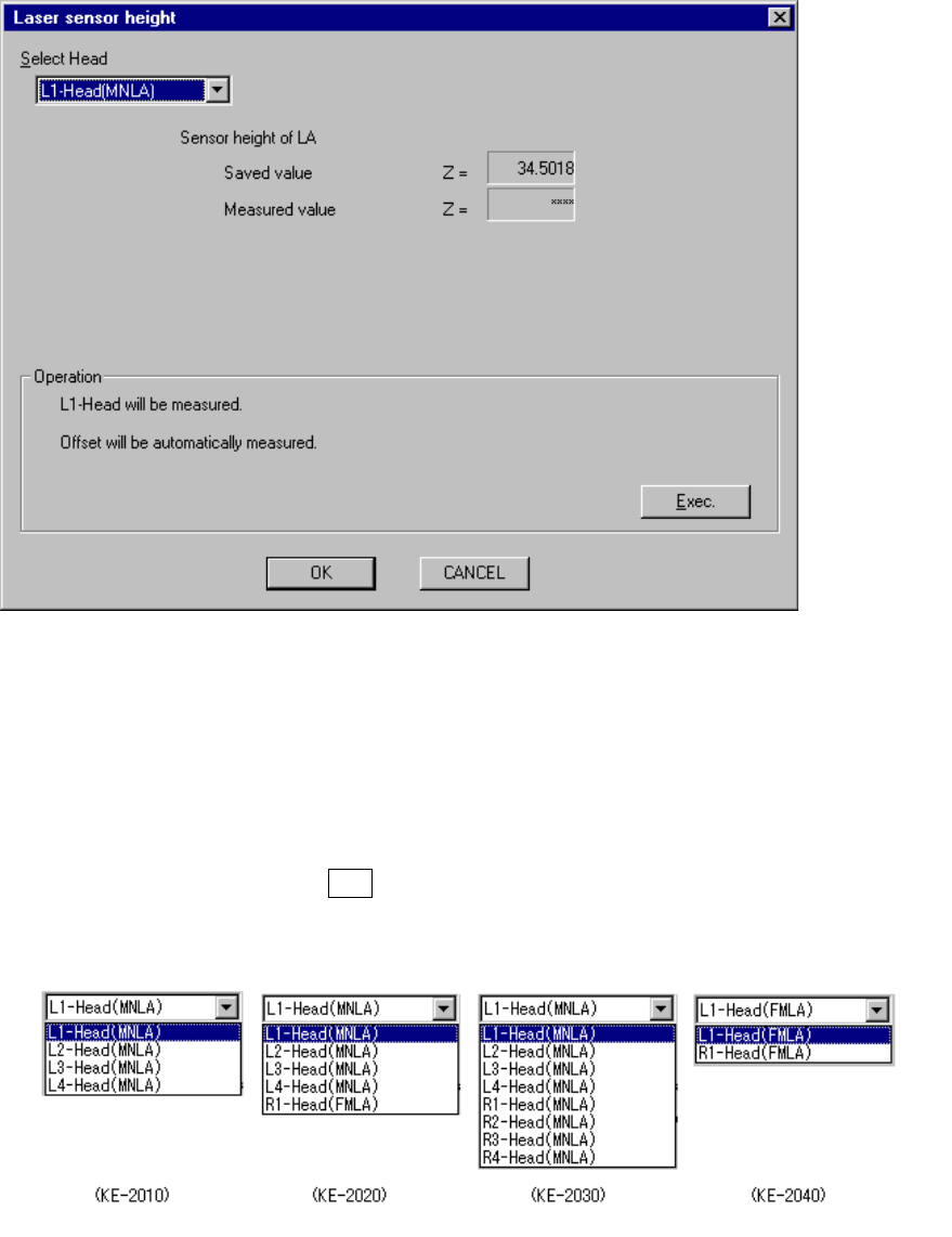
When you select the [Set-up group] command on the menu bar, then select the
[Laser sensor height] command on the displayed menu, the following “Laser sensor
height” dialog box appears on the screen.
Figure 10.3.1 “Laser sensor height” screen
− Select Head
Using this combo box, select the head to be set.
The units which are not checked on the “Device enable” menu invoked from the
Machine Setup menu (that is, checked as “Not used”) cannot be selected
When you press the ALT key and the down arrow key at the same time, the
following list appears on the screen.
(When the left 1
head is selected)
(Height already set)
(Height measured)
10 − 6
(1) Setting items
No. Item Description
1 Sensor height of LA Height of the laser sensor viewed from the top of a board
(2) How to set
− For the head selected in the “Select Head” combo box, set the various values
by followings the instructions displayed on the dialog box.
− When you click the <OK> button, your setting becomes valid (but not be
saved at this point).
− When you click the <CANCEL> button, your setting becomes invalid.
− How to operate
By following the instructions displayed, the appropriate value is automatically
obtained.
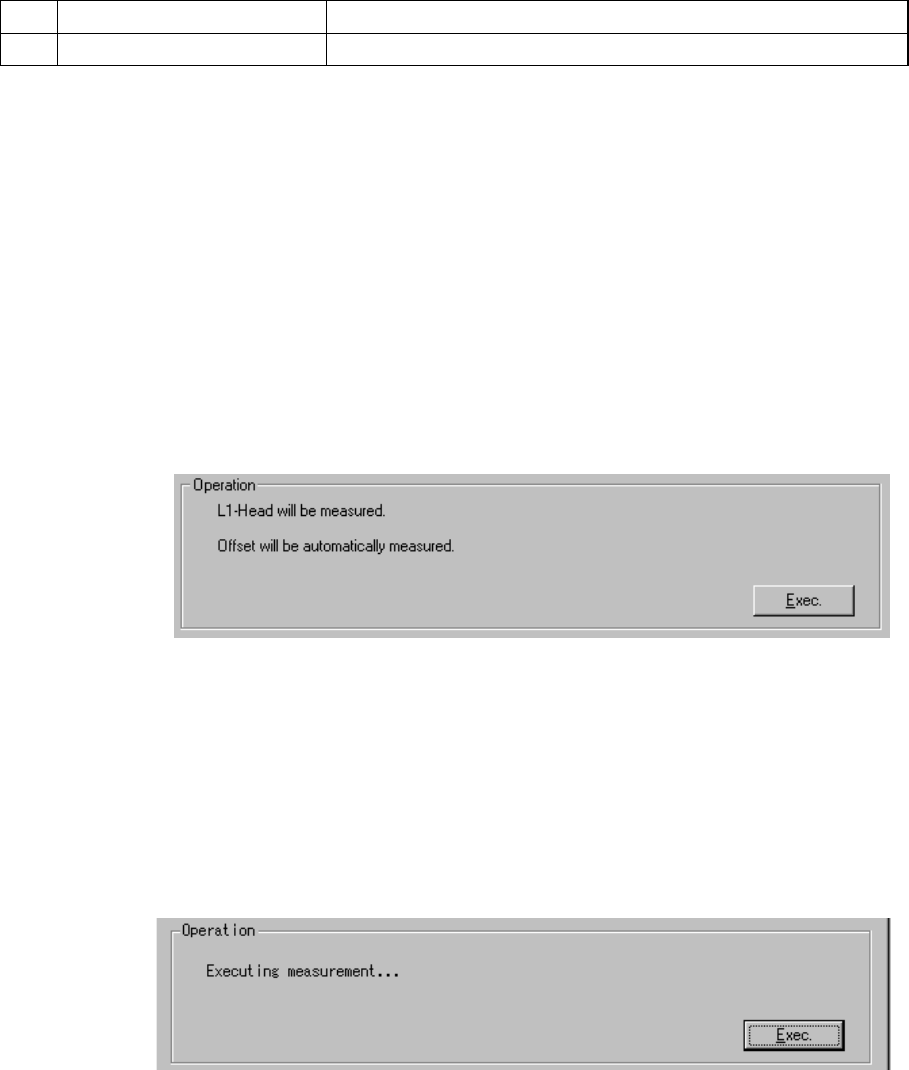
(When the left 1 head is selected)
The head selected in the “Select Head” combo box is to be set.
Select the <Exec.> button.
When you select the <Exec.> button, the nozzle (No. 500, 501 or 502) is
attached onto the head, and the laser sensor height is automatically
measured.
− Measurement operation
① The nozzle (No. 500, 501 or 502) is attached on the selected head.
An error occurs if the nozzle is not set for the ATC. In this case, assign
the nozzle on the “ATC nozzle setup” menu which is invoked from the
Machine Setup menu.