KE2010.Instruction Manual.Ver.2.01,Rev.08.pdf - 第31页
1 − 14 1.1.5 Electrical specifications (1) Number of placement point s Up to 3,000 placement points can be def ined per pr ogram . For multi-mat rix PW Bs, up to 10,000 points can be def ined, which is the number of cir …
1 − 13
(10) Environmental conditions
Operating
Ambient temperature: +10° C to +35° C
Relative humidity: 50% or less (at 35° C)
90% or less (at 20° C)
Transport and storage
Temperature: -25° C to +70° C
Relative humidity: 20% to 95% (No condensation)
(11) Installation category: Installation category II (IEC664-1)
(12) Pollution degree: Pollution degree II (IEC664-1)

1 − 14
1.1.5 Electrical specifications
(1) Number of placement points
Up to 3,000 placement points can be defined per program.
For multi-matrix PWBs, up to 10,000 points can be defined, which is the number
of circuits multiplied by the number of placement points.
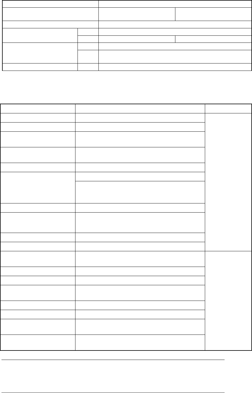
(2) Control Systems
Table 1.1.5.1
Item Control system Resolution
X-Y
Z
θ (head)
Closed loop by AC servo motor
Semi-closed loop by AC servo motor
Semi-closed loop by AC servo motor
0.005mm
0.00125mm
0.02°
(3) Main CPU
Pemtium
(4) Display
Character display : 10.4" color (TTF liquid crystal display panel)
Graphics display : 9" monochrome
(5) Data and program input/output
A program which has been generated with an external programming device or
manually created from the keyboard can be input by means of a 3.5" floppy disk.
(2HD/1.44 MB type only)
When the machine is connected to a host line computer, the LAN interface
permits high-speed communications.
(6) Printer interface
Centronics interface
(7) Power requirements
Voltage : Three-phase, 200 V, 220 V, 240 V
(for Japan)
200 V, 220 V, 240 V, 380 V, 400 V, 415 V
AC
(for the machines to be exported)
Allowable voltage range: ± 10 % (for the rated voltage)
Apparent power : 3 kVA
Frequency : 50/60 Hz
Size of the primary-side power cable : 6 mm
2
or more
Size of the protective grounding lead wire : 6 mm
2
or more
(8) UPS
This machine is equipped with the uninterruptible power supply (UPS) to prevent
data from being damaged or lost due to power failure.
Batteries are used as the back-up power supply of the UPS, so the UPS is
designed to stop the system before these batteries run down. Therefore, even
during power failure, the system can be terminated safely so that any data cannot
be damaged or lost even when a power failure occurs.
1 − 15
1.1.6 Applicable components and packages
(1) Applicable component sizes (For laser recognition)
Item Specifications
Component height specifications 6 mm
20 mm (option at the
factory)
Head Laser recognition (MNLA)
Min. 0.2 mm
Component height
Max. 6 mm
20 mm
Min. 0.6 mm x 0.3 mm
Component size
(Length x Width)
Max. 20 mm x 20 mm or 26.5 mm x 11 mm
(Diagonal line should be 30.7 mm or less.)
Lead pitch Min. 0.65 mm
(2) Applicable component
Table 1.1.6.1
Component Name Shape Package
Square chip resistor 0603, 1005, 1608, 2012, 3216, 3225 (5025, 6432)
Network resistor (Excluding SOP, SOJ, PLCC types)
MELF resistor 1.6 x φ1.0mm, 2.0 x φ1.25mm, 3.5 x φ1.4mm,
5.9 x φ2.2 mm
Laminated ceramic
capacitor
0603, 1005, 1608, 2012, 3216, 3225, 4532, 5750
(5632)
Tantalum chip capacitor 3216, 3528, 6032, 7343
6.0 mm or less Aluminum electrolytic
capacitor Height:
10.5 mm or less
(applicable if the component height specifications
is 20 mm.)
Chip film capacitor
Variable trimmer capacitor,
Chip potentiometer,
trimmer
Chip ferrite beads
Chip inductor
Tape
SOT molded part 1608/2012, SOT-23,
SOT-89, SOT-143, SOT-223
SOP 8, 14, 16, 18, 20, 24, 28,32-pin
SOJ 16, 18, 20, 24, 26, 28-pin
PLCC 18, 20, 22, 28 (Square), 28 (Rectangle),
32, 44-pins
QFP, BQFP Lead pitch: 0.65 mm or less □20mm or less
BGA
□
20mm or less
Connector
□
20mm or less with 0.65mm or less pitch,
Laser recognition must be possible.
IC socket □20mm or less with 0.65mm or more pitch,
Laser recognition must be possible.
Tape
Stick
Tray
Note:
Four nozzles can pick up components whose size is 10 mm x 10 mm
or less simultaneously.
Two nozzles (No. 1 and 3 or No. 2 and 4: one nozzle is skipped) can
pick up components whose size is larger than 10 mm x 10 mm
simultaneously.