KE2010.Instruction Manual.Ver.2.01,Rev.08.pdf - 第145页
4 – 38 4.5 PWB Data 4.5.1 Basic setting Aft er the Prog ram Editing ut ility start s up or when you select [Create new] on the File menu, a prog ram name becomes “ UNTIT LED”, and t he PW B data basic setup screen as sho…
4 – 37
4.4 Data
This command menu provides the commands which allows you to move to the Editing
screen for each type of data: PWB data, Placement data, Component data, and
Pick data, and those for displaying each type of data completion status, and those for
checking to see if each data record is completed correctly by comparing to the
configuration set on the Setup screen.
4.5 PWB data
4.6 Placement data
4.7 Component data
4.8 Pick data
The commands above display the corresponding type of data and switch the input
screen for each type of data.
See the Section on each type of data for details.
Other method for switching the data input screen
In addition to the method described above, you can switch between each type of data
input screens as described below.
① Press the F6 key while holding the CTRL key or press the TAB key while holding
the CTRL key to move to the next data window. Press the F6 key while
holding the SHIFT and CTRL keys or press the TAB key while holding the SHIFT
and CTRL keys to move to the previous data window.
② Click each data title button displayed on the bottom of the screen.
4 – 38
4.5 PWB Data
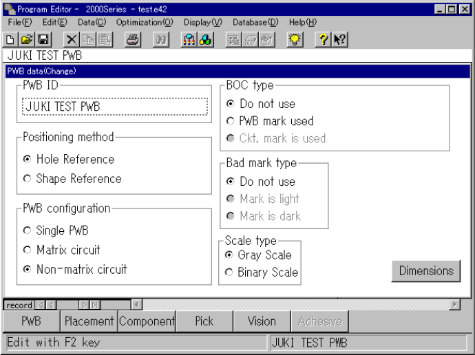
4.5.1 Basic setting
After the Program Editing utility starts up or when you select [Create new] on the File
menu, a program name becomes “UNTITLED”, and the PWB data basic setup screen
as shown in the figure below appears initially.
Use the "PWB ID" edit box to set the PWB ID, and use the corresponding radio button
to set the positioning method, PWB configuration, BOC type and bad mark type.
To set each item, move the cursor over the desired item with a track ball, then click
the button of the desired setting with the left button.
Description of each menu item
(1) PWB ID
Up to 32 alphanumeric characters and symbols can be entered. However, note
that only numbers or only symbols cannot be entered. They shall be combined
with alphabetic characters. When reading the production program, the PWB ID
is displayed as well as the file name of the production program, so enter an ID
which is easy to understand.
(2) Positioning method
1) Hole reference
The PWB has positioning holes, and the reference pins are inserted in the
holes to hold the PWB.
2) Shape reference
After the PWB touches the stopper, the edges of the PWB are fixed
mechanically to hold the PWB.
4 – 39
(3) PWB configuration
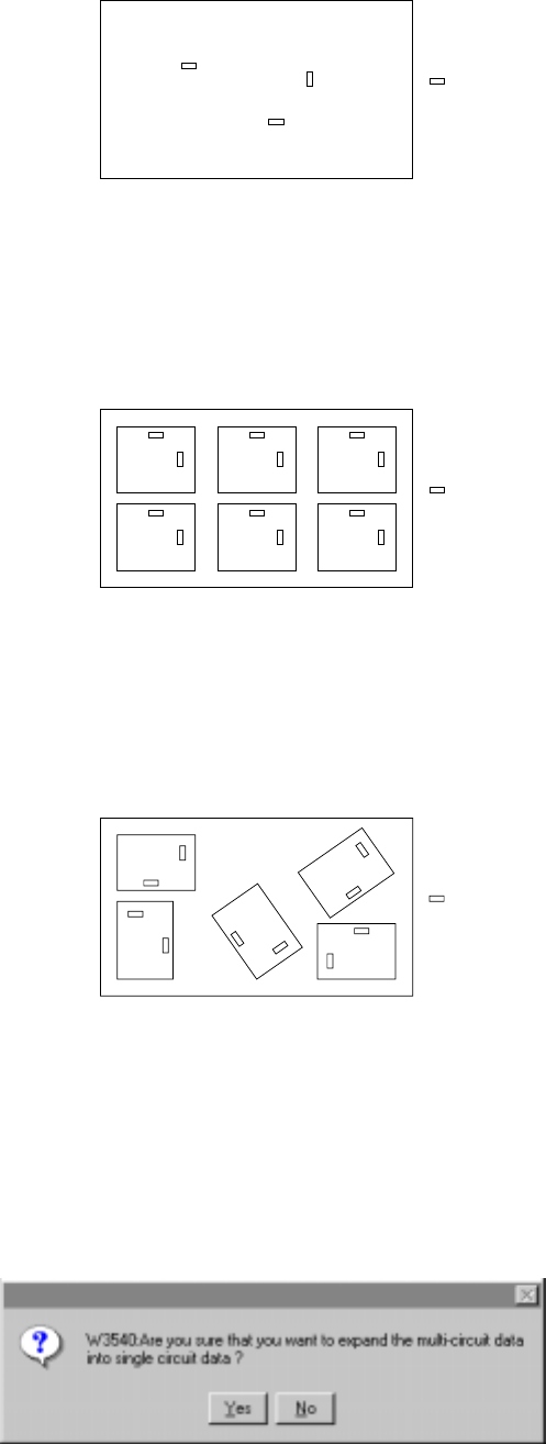
1) Single PWB
The PWB which has only one circuit pattern.
Figure of the single pattern
2) Multiple PWB matrix
The PWB which has multiple circuit patterns aligned in depth and width and
with a same angle and space.
Figure of the Matrix multiple patterns
3) Multiple PWB non-matrix
The PWB which has multiple circuit patterns but with a different angle and
space among them.
Figure of the Non-matrix multiple patterns
Note that circuits are automatically assigned in the multiple PWB non-matrix
pattern if you change the PWB configuration from the multiple PWB matrix
pattern to the multiple PWB non-matrix pattern after setting the dimensions for
the multiple PWB matrix pattern. If you change the PWB configuration from the
multiple PWB matrix or multiple PWB non-matrix pattern to the single PWB
pattern, a PWB is configured as one circuit, and the confirmation message
appears on the screen.
Component
Component
Component