KE2010.Instruction Manual.Ver.2.01,Rev.08.pdf - 第746页
12 − 16 This unit allows the machine t o collect components which are not placed on a boar d for some reason without damag ing them aft er the component s are recog nized with the VCS. Components which are placed on the …
12 − 15
12.10 Handling the IC Collection Belt
1. Specifications
(1) Applicable components
Component type: QFP, SOP, PLCC and so on
(components recognized with the VCS)
Component size: 10 mm x 10 mm to 50 mm x 50 mm, 1.0 mm to 6.0 mm
(2) Number of ICs to be collected
5 to 19 (this number varies depending on the size of an IC)
(3) How much the belt is to be fed
15 mm to 55 mm (in increments of 5 mm): manually set the rotary switch
according to the size of an IC to be collected.
(4) Belt
Anti-static belt: width 5 mm
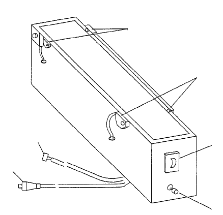
2. Configuration and parts identification of the IC collection belt
Figure 12.10.1 Parts identification of the IC collection belt
① Component sensor
② Stop sensor
③ IC size setting rotary switch
④ Reset switch
⑤ Power plug
⑥ ALARM signal connector
①
②
③
④
⑤
⑥
12 − 16
This unit allows the machine to collect components which are not placed on a board for
some reason without damaging them after the components are recognized with the
VCS.
Components which are placed on the component sensor ① from the head are fed
sequentially at the pitch selected with the rotary switch ③.
When the belt is full of components and the Stop sensor ② detects a component, the
main unit pauses and displays the message on the screen.
CAUTION
To avoid a risk of injury and prevent the machine from being damaged,
be sure to collect components only after detaching the IC collection belt
from the feeder bank or after you check to see if the machine stops
completely.
If you are to collect components from the IC collection belt being fixed
on the feeder bank, be sure to check to see if there is no person who
may start the machine unexpectedly.
3 Attaching and detaching the IC collection belt
(1) Place the bottom of the IC collection belt ① on the feeder bank ②.
(2) Slide the IC collection belt to align the front positioning pin ⑤ of the IC collection
belt with the fixing hole of the fixing plate ③. Align the lock holder ⑦ with the
V-shaped groove of the lock shaft ⑥, then push the lock holder until it becomes
in contact with the fixing plate ③. Connect the power plug ⑧ of the IC
collection belt to the jack ⑨ of the main unit, and the ALARM signal connector
⑩ to the relay cable.
Note: Check to see if the IC collection does not float nor be tilted.
(3) To detach the IC collection belt,
pull the IC collection belt ①
toward the rear while pulling the
lever of the lock holder ⑦ to
detach it.
Figure 12.10.2 Attaching/detaching the IC collection belt
CAUTION
To avoid any accident caused by sudden activation of the machine,
turn off the power.
12 − 18
12.11 Handling a Portable Type Tray Server (DTS)
If you attach or remove a DTS while the XY axis or head is operating,
the DTS may come in contact with a part that is moving, and you may
be injured or the machine may be damaged.
Do not attach or remove any DTS onto/from the machine while the XY
axis or head is operating.
After attaching the DTS onto the machine, secure the safety by
eliminating any clearance into which your hand or finger happens to be
put, for example by attaching an unused tape feeder on the clearance.
Procedure for attaching/removing a DTS
Refer to the Instruction Manual supplied with the DTS.
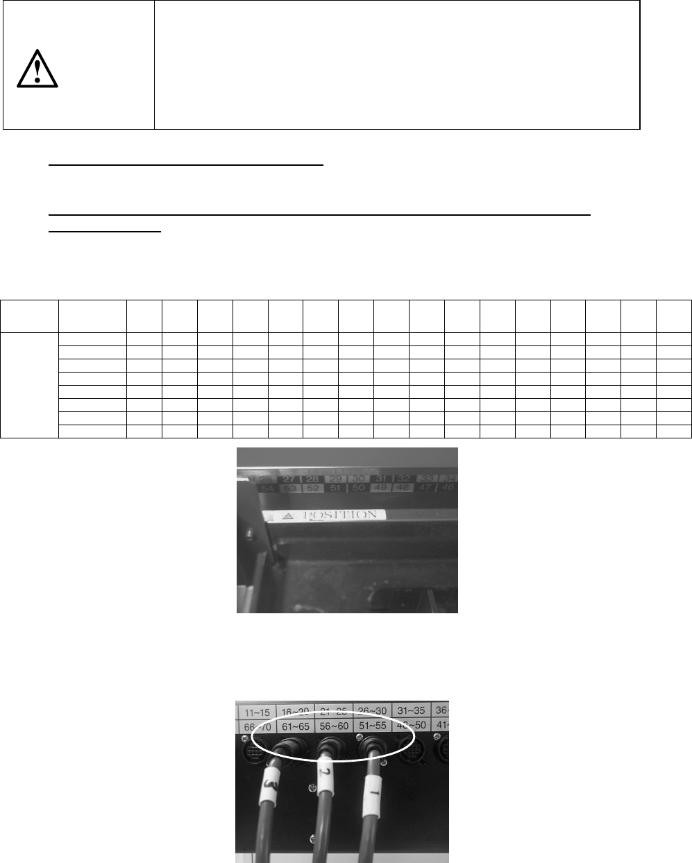
Attaching position (relation between the feeder bank number and the connector
bracket number)
The position of the DTS cable to be connected to the connector bracket may vary
depending on the feeder bank number the DTS is to use.
Table 12.11 DTS cable position
Feeder
bank
number
76~79 71~75 66~70 61~65 56~60 51~55 46~50 41~45 36~40 31~35 26~30 21~79 16~20 11~15 6~710 1~5
Rear 76 to 77 ① ② ③
Rear 71 to 75 ① ② ③
Rear 66 to 70
① ② ③
Rear 61 to 65
① ② ③
Rear 56 to 60 ① ② ③
Rear 51 to 55
① ② ③
Rear 46 to 50
① ② ③
Connector
bracket
number
Rear 45 ① ② ③
*
①
: DTS P1-3-pin connector
②: DTS P2-3-pin connector
③: DTS P3-3-pin connector
Figure 12.11.1 Example: When “
△
POSITION” is set to the number 53 (it is
assumed that this is set as the device enabled on the Setup menu).
The feeder bank numbers “51 to 55” are applied to this unit according to the table
above.
Figure 12.11.2 onnect the No.
①
connector to the connector bracket number “51
to 55”, No.
②
connector to “56 to 60” and No.
③
connector to “61 to 65.”
CAUTION