KE2010.Instruction Manual.Ver.2.01,Rev.08.pdf - 第57页
1 − 40 Table 1.4.1 List of connector s on the left side panel Signal name (left to right) Signal name (right to left) Connector used 1 READY OUT READY IN 2 READY OUT READY IN GND 3 BOAD AVAILABLE IN BOAD AV…
1 − 39
⑥
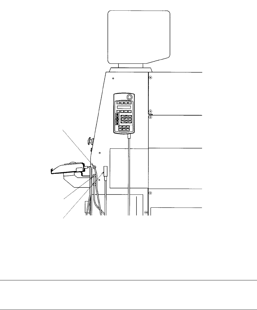
is a 9-Pin connector for the trackball.
See Table 1.4.5 for the pin assignment of this trackball connector.
⑦
is a 50-Pin connector for the keyboard.
See Table 1.4.4 for the pin assignment of this keyboard connector.
⑧
is a 5-Pin connector for the Hand-held operating device (HOD).
Figure 1.4.3 Machine right side panel
Note: The shape of the track ball connector and that of the keyboard connector is
the same. If you accidentally make the wrong connections, the system will
not be started up.
⑥
⑧
⑦
1 − 40
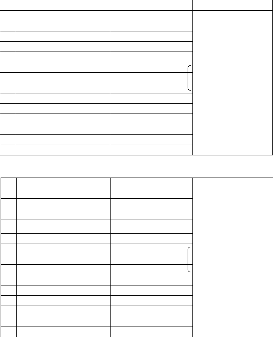
Table 1.4.1 List of connectors on the left side panel
Signal name (left to right) Signal name (right to left) Connector used
1 READY OUT READY IN
2 READY OUT READY IN GND
3 BOAD AVAILABLE IN BOAD AVAILABLE OUT
4 BOAD AVAILABLE IN GND BOAD AVAILABLE OUT
5 N.C. N.C.
6 N.C. N.C.
7 N.C. N.C.
8 N.C. N.C.
9 N.C. N.C.
10 N.C. N.C.
11 N.C. N.C.
12 N.C. N.C.
13 N.C. N.C.
14 N.C. N.C.
Table 1.4.2 List of connectors on the right side panel
Signal name (left to right) Signal name (right to left) Connector used
1
READY IN READY OUT
2
READY IN GND READY OUT
3
BOAD AVAILABLE OUT BOAD AVAILABLE IN
4
BOAD AVAILABLE OUT BOAD AVAILABLE IN
GND
5
N.C. N.C.
6
N.C. N.C.
7
N.C. N.C.
8
N.C. N.C.
9
N.C. N.C.
10
N.C. N.C.
11
N.C. N.C.
12
N.C. N.C.
13
N.C. N.C.
14
N.C. N.C.
(Connection of the
cable end 206044-1)
AMP
206043-1
(Connection of the
cable end 206044-1)
AMP
206043-1
1 − 41
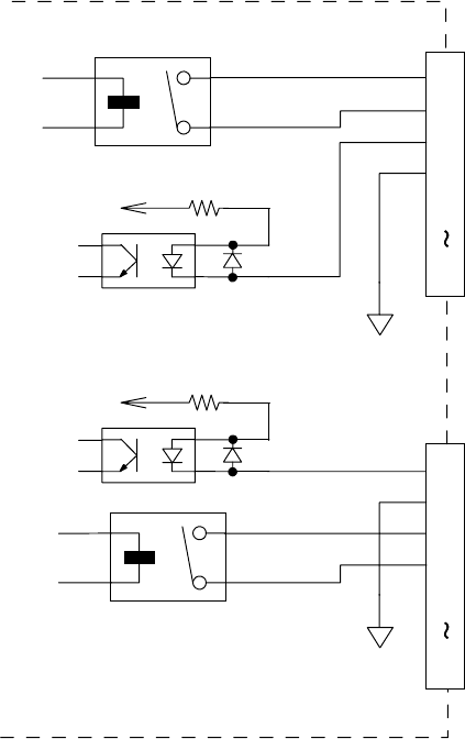
Figure 1.4.4 shows the interface circuits for READY OUTs (IN) and BOARD
AVAILABLE signals.
They conform to the SMEMA standard.
GND(24V)
+
+24V
3.3K 1/4W
READY OUT +
BOAD AVAILABLE IN +
READY OUT -
BOAD AVAILABLE IN -
N.C.
1
2
3
4
5
14
READY IN +
BOAD AVAILABLE OUT +
READY IN -
BOAD AVAILABLE OUT -
N.C.
1
2
3
4
5
14
+24V
3.3K 1/4W
+
GND(24V)
Figure 1.4.4