KE2010.Instruction Manual.Ver.2.01,Rev.08.pdf - 第248页
4 – 141 (3-4) Coher ence check item s: error conditions Data ty pe Item Error conditions Line The line cannot handle V ision data. *1 Placement of vision components (over 0.4 mm) (Lead components) The standard VCS or opt…
4 – 140
Data type Item Error conditions
If the “Sequential and Mix Mode” is selected at the menu item
“2030 Mode Specification” of the “2000 Option” tab, “Use
permanent nozzle setup from MSL Setup” is selected at the
menu item “Nozzle” of the “Assignments” tab of the
“Optimization” menu, the menu item “SPLY” (supply) is all
entered to the pick data on the same component on the Pick
data screen that is associated with Component data, and a
nozzle specified on the Component data screen does not
exist on both of the stations.
Note that if a nozzle is located at either of both stations when
Pick data is set to both stations, the system will not handle
this situation as an error.
Pick data Nozzle (for a KE-2030)
If the “Sequential and Mix Mode” is selected at the menu item
“2030 Mode Specification” of the “2000 Option” tab, “Auto
arrange empty nozzle positions” is selected at the menu item
“Nozzle” of the “Assignments” tab of the “Optimization” menu,
the menu item “SPLY” (supply) is all entered to the pick data
on the same component on the Pick data screen that is
associated with Component data, and a nozzle specified on
the Component data screen does not exist on both of the
stations.
Note that if a nozzle is located at either of both stations when
Pick data is set to both stations, the system will not handle
this situation as an error.

4 – 141
(3-4) Coherence check items: error conditions
Data type Item Error conditions
Line The line cannot handle Vision data. *1
Placement of vision
components (over 0.4 mm)
(Lead components)
The standard VCS or optional VCS (37.5 mm, 27 mm or
18 mm) is not set in Placement data of vision
components whose size is 0.4 mm or larger.
*1
Placement of vision
components (0.3 <= Pitch < 0.4
mm) (Lead components)
The optional VCS (37.5 mm, 27 mm or 18 mm) is not
set in Placement data of vision components whose pitch
is 0.3 mm or wider, but narrower than 0.4 mm.
*1
Placement of vision
components (0.2 <= Pitch < 0.3
mm) (Lead components)
The optional VCS (27 mm or 18 mm) is not set in
Placement data of vision components whose pitch is 0.2
mm or wider, but narrower than 0.3 mm.
*1
Placement of vision
components (0.135 <= Pitch <
0.2 mm) (Lead components)
The optional 18 mm VCS is not set in Placement data of
vision components whose pitch is 0.135 mm or wider,
but narrower than 0.2 mm.
*1
Placement of general vision
components (15 < the smallest
pitch <= 22 mm) (Lead
components)
The standard VCS is not set in Placement data of
general vision components whose minimum pitch is
wider than 15 mm, but 22 mm or narrower.
*1
Placement of general vision
components (11 < the smallest
pitch <=15 mm) (Lead
components)
The standard VCS or optional 37.5 mm VCS is not set
in Placement data of general vision components whose
minimum pitch is wider than 11 mm, but 15 mm or
narrower.
*1
Placement of general vision
components (6.5 < the smallest
pitch <= 11 mm) (Lead
components)
The standard VCS or optional 37.5 mm or 27 mm VCS
is not set in Placement data of general vision
components whose minimum pitch is wider than 6.5
mm, but 11 mm or narrower.
*1
Placement of general vision
components (0.5 <= the
smallest pitch <=6.5 mm)
(Lead components)
The standard VCS or optional 37.5 mm, 27 mm or 18
mm VCS is not set in Placement data of general vision
components whose minimum pitch is 0.5 mm or wider,
but 6.5 mm or narrower.
*1
Placement of general vision
components (0.4 <= the
smallest pitch <0.5 mm) (Lead
components)
The optional 37.5 mm, 27 mm or 18 mm VCS is not set
in Placement data of general vision components whose
minimum pitch is 0.4 mm or wider, but narrower than 0.5
mm.
*1
Placement of general vision
components (0.3 <= the
smallest pitch < 0.3 mm) (Lead
components)
The optional 27 mm or 18 mm VCS is not set in
Placement data of general vision components whose
minimum pitch is 0.3 mm or wider, but narrower than 0.4
mm.
*1
Placement of general vision
components (0.2 <= the
smallest pitch < 0.3 mm) (Lead
components)
The optional 18 mm VCS is not set in Placement data of
general vision components whose minimum pitch is 0.2
mm or wider, but narrower than 0.3 mm.
*1
Placement of vision
components (15 < the smallest
pitch <= 22 mm) (Ball
components)
The standard VCS is not set in Placement data of vision
components whose minimum pitch is wider than 15 mm,
but 22 mm or narrower.
*1
Placement of vision
components (11 < the smallest
pitch <15 mm) (Ball
components)
The standard VCS or optional 37.5 mm VCS is not set
in Placement data of vision components whose
minimum pitch is wider than 11 mm, but 15 mm or
narrower.
*1
Placement of vision
components (6.5 < the smallest
pitch <= 11 mm) (Ball
components)
The standard VCS or optional 37.5 mm or 27 mm VCS
is not set in Placement data of vision components
whose minimum pitch is wider than 6.5 mm, but 11 mm
or narrower.
*1
Vision data
Placement of vision
components (1.0 <= the
smallest pitch < 6.5 mm) (Ball
components)
The standard VCS optional 37.5 mm, 27 mm or 18 mm
VCS is not set in Placement data of vision components
whose minimum pitch is wider than 1.0 mm, but 6.5 mm
or narrower.
*1
*1: Items applicable to machines other than a KE-2010
4 – 142
Data type Item Error conditions
Placement of vision
components (0.8 <= the
smallest pitch < 1.0 mm) (Ball
components)
The optional 37.5 mm, 27 mm or 18 mm VCS is not set
in Placement data of vision components whose
minimum pitch is 0.8 mm or wider, but narrower than 1.0
mm.
*1
Placement of vision
components (0.5 <= the
smallest pitch < 0.8 mm) (Ball
components)
The optional 27 mm or 18 mm VCS is not set in
Placement data of vision components whose minimum
pitch is 0.5 mm or wider, but narrower than 0.8 mm.
*1
Placement of vision
components (0.35 <= the
smallest pitch < 0.5 mm) (Ball
components)
The optional 18 mm VCS is not set in Placement data of
vision components whose minimum pitch is 0.35 mm or
wider, but narrower than 0.5 mm.
*1
Pick-up of all balls or all lands
vision recognition components
The BGA vision recognition function cannot be used with
the station in Pick data of all balls or all lands vision
recognition components.
*1
Number of all balls or all lands
vision recognition ball pattern
components
The number of user-defined ball pattern components in
Pick data is found to exceed 10 with the all balls or all
lands vision recognition function.
*1
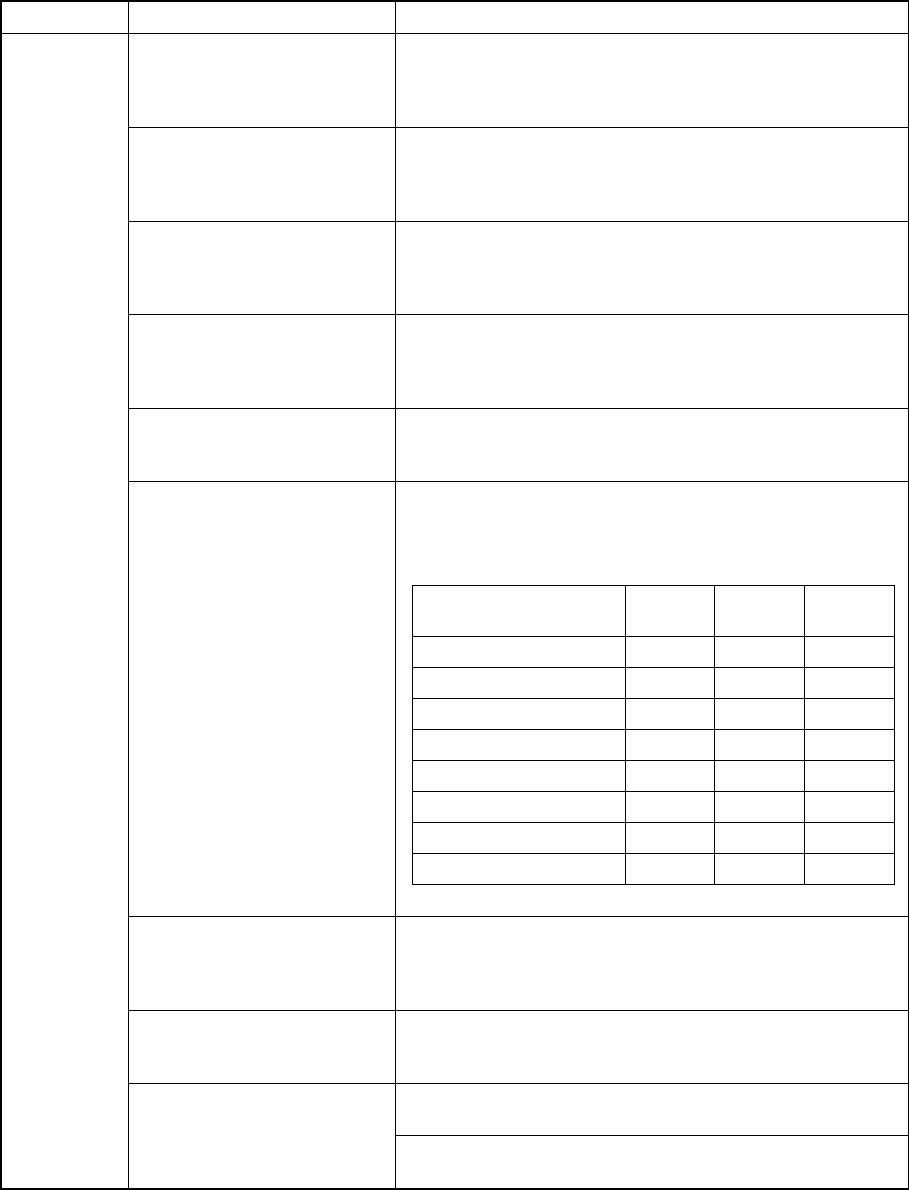
Error conditions of the VCS recognition type specified on
the MSL setup menu and the light type specified in Light
data
*1
VCS recognition type
Reflective
light
Penetra-
tive light
Side light
No recognition × × ×
BGA vision recognition × × ○
Penetrative recognition
× ○ ×
Reflective recognition
○ × ×
BGA, penetrative
× ○ ○
BGA, reflective
○ × ○
Penetrative, reflective
○ ○ ×
BGA, Penetrative, reflective
○ ○ ○
Light type
Component for which you can
select “Vision centering
component” as its component
type
The component size is smaller than 0.6 mm.
For components that undergo
coplanarity inspection (2000
series only)
The longer side of the component size exceeds 50 mm
and the height of the component exceeds 8.00 mm.
*1
The “standard measurement mode” is selected and the
longer side of the component size exceeds 100 mm.
*1
Coplanarity measurement
mode
The “high-accuracy measurement mode” is selected and
the longer side of the component exceeds 50 mm.
*1