KE2010.Instruction Manual.Ver.2.01,Rev.08.pdf - 第503页
6 − 127 ⑥ Manual pick -up If there is no Pick data, you can attach a com ponent on a nozzle manually. I n such a case, you cannot enter any coordinate of a component pick-up posit ion. You cannot operate any f eeder eith…
6 − 126
③
Returning a component after checking it
The system returns some checked components onto their original positions, or
discards other ones depending on their packaging style as shown in Table
below (6.7.1.2). Where to discard a component is determined according to the
setting of “Compo Reject to” on the Component data screen. The system
discards a checked component when the menu item “Compo Reject to” is set to
“Trash conveyor” or “Protect.”
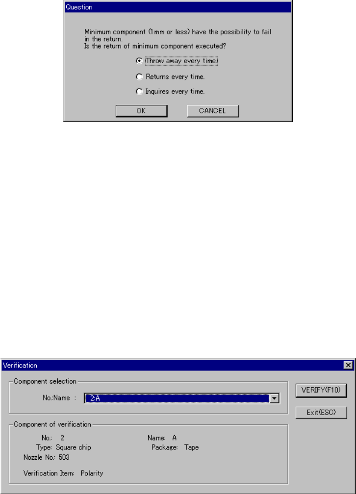
− Since a component whose size is 1 mm or less may stand on its side or
may be turned upside down when it is returned to the original position, the
system displays the “Question” dialog box shown in Figure 6.7.1.2.1 to ask
you how it should handle a component.
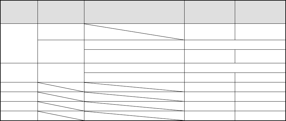
Table 6.7.1.2 Requirements for returning/discarding a component
Packaging
style
Requirement 1 Requirement 2 When
returning a
component
When
discarding a
component
32-mm tape
feeder
− ○
The shorter side is 1 mm or shorter. Question dialog box *1
Tape
Tape feeders
other than the
above
The shorter side is 1 mm or longer. ○ ○ *2
The shorter side is 1 mm or shorter. Question dialog box *1
Bulk −
The shorter side is 1 mm or longer. ○ ○ *2
Holder ○ ○ *2
MTC ○ ○ *2
MTS ○ ○ *2
Stick − ○
*1 The system displays the dialog box to prompt you to select whether to return or
discard a component. When the system is set to measure components
continuously, it displays the dialog box at start of continuous measurement.
*2 The system discards a checked component when the menu item “Compo Reject
to” is set to “Trash conveyor” or “Protect.”
④
Selecting a feeder used to pick a component
If tow or more feeders are assigned to the same type of components on the
Pick data screen, the system starts picking up components from one whose
data was entered first of all by default.
Only in Single check mode, you can change the feeder used to pick up a
component intentionally (see Figure 6.4.4.3.2).
⑤
Changing the coordinates of a component pick-up position
When a component is not picked up properly, manually enter the coordinates or
use the HOD device to teach them to change the coordinates of a component
pick-up position.
6 − 127
⑥
Manual pick-up
If there is no Pick data, you can attach a component on a nozzle manually. In
such a case, you cannot enter any coordinate of a component pick-up position.
You cannot operate any feeder either.
Figure 6.7.1.2.1 “Question” dialog box
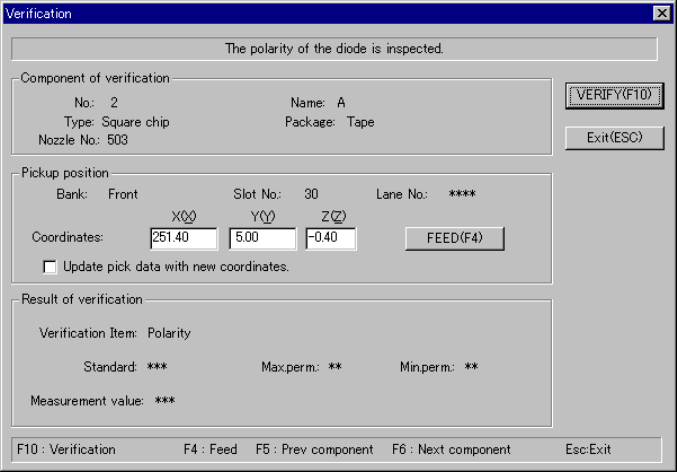
6.7.1.3 Single verification check
6.7.1.3.1 “Verification” component selection dialog box
When you select the [Tool] command from the menu bar, the [Check] command on
the “Tool” menu, and the [Verification] command on the Production menu, the
following dialog box appears on the screen.
− The “NO.:Name” combo box lists square chips whose menu item “Verify” is set
to “Yes” on the Component data screen.
− Select a component to be checked.
Figure 6.7.1.3.1 “Verification” single check component selection dialog box
6 − 128
6.7.1.3.2 “Verification” single check dialog box
When you click the <VERIFY> button on the “Verification” component selection
dialog box shown in Figure 6.7.1.3.1, the following dialog box appears on the
screen.
Figure 6.7.1.3.2 “Verification” single check dialog box
− Component of verification
Data on a component selected to be checked appears here.
− Pickup position
Data on the component pick-up position appears here. You can change the
pick-up position to that of the previous alternate component or the next
alternate component also.
①
<FEED> button
When you click this button, the system knocks a feeder once to feed a
component (not available with a 32-mm paper tape).
②
Check box “Update pick data with new coordinates.”
Check this check box if you want to store the result of teaching operation by
the HOD device onto Pick data.
− If you do not check this check box, the specified coordinates are applied
to the current pick-up position only.
− Result of verification
The “Verification item”, “Standard” value, the upper limit of allowable values
(“Max.perm.”) and the lower limit of allowable values (“Min.perm.”) appear
here.
− After checking a component, the system displays the measured value at
the item “Measurement value”.